Method and apparatus for flotation in a fluidized bed

a technology of fluidized bed and flotation method, which is applied in the direction of flotation, solid separation, etc., can solve the problems of high energy-dissipation rate, difficult flotation of coarse particles, and severe limitations of existing technologies in regard to their ability to recover coarse particles

Active Publication Date: 2010-08-05
UNIV OF NEWCASTLE RES ASSOCS
View PDF15 Cites 29 Cited by
  • Summary
  • Abstract
  • Description
  • Claims
  • Application Information

AI Technical Summary

Problems solved by technology

It is well established that coarse particles are difficult to float because of the effect of turbulence in the flotation machines in current use.
It is clear that existing technologies have a severe limitation in regard to their ability to recover coarse particles.
This device suffers from an important deficiency in relation to the flotation of coarse particles, since it depends on the suspending action of the impeller, which will inevitably introduce high energy-dissipation rates throughout the flotation cell, and create high levels of turbulence that will cause coarse particles to detach from the bubbles.
However, this invention has severe limitations if used for flotation.
In flotation, it is desired to separate the hydrophobic particles from the hydrophilic particles, and the Mankosa device cannot do this.
The inability to distinguish between particles that arrive in the collection launder because they are of lower density than those in the underflow discharge, and those that are present because they are hydrophobic and have become attached to air bubbles, is a very severe limitation from the point of view of the flotation process.
Another weakness of this invention is the necessity to use clean water as the fluidizing fluid.

Method used


Image

  • Method and apparatus for flotation in a fluidized bed
  • Method and apparatus for flotation in a fluidized bed
  • Method and apparatus for flotation in a fluidized bed

Examples


Embodiment Construction

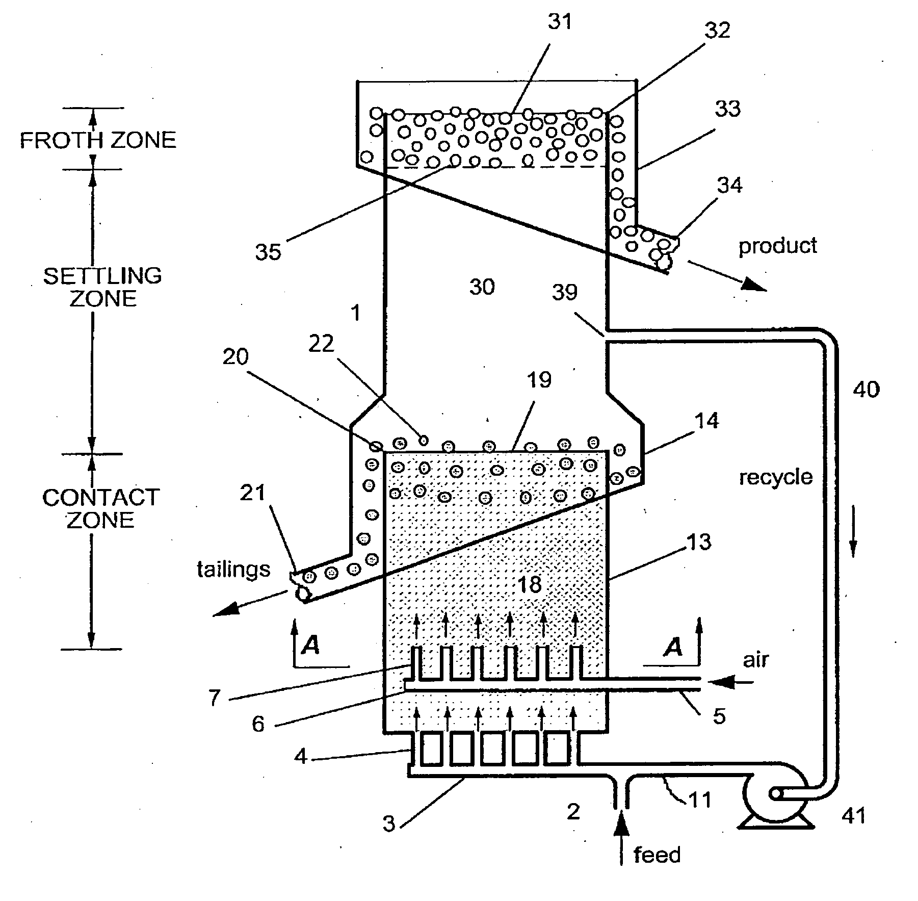
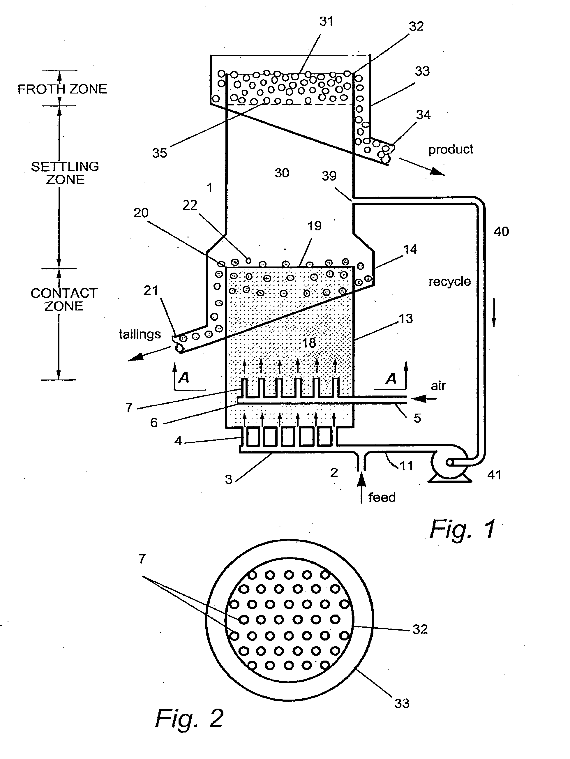
[0048]FIGS. 1 and 2 show a cross-sectional elevation and a plan view respectively, of a first preferred embodiment according to the invention. The liquid feed containing the particles to be separated by flotation is prepared and conditioned with appropriate collector and frother reagents prior to entry to the vessel or column 1. For convenience it will be assumed that the vessel is a column with rotational symmetry about the vertical axis. The base of the column is a vertical cylindrical section 13, at the top of which an internal launder 14 is located. The feed to the column enters at the inlet 2, where it mixes with a supply of recycle liquid entering from a duct 11. The two streams combine and enter a distribution system 3 that feeds a multiplicity of entry pipes 4 into the base of the flotation cell. The total water flowrate is such that the superficial water velocity in the cell exceeds the minimum value required for fluidization. Air is introduced into the cell through a duct ...


PUM


Abstract

Separation of hydrophobic particles from a mixture of particles in a fluid is performed by providing a fluidized bed as a relatively non-turbulent contacting mechanism in a flotation cell incorporating a settling chamber located immediately above the fluidized bed. Hydrophobic particles attach to bubbles in the fluidized bed and rise to the interface with the settling chamber where non-hydrophobic particles flow over the lip of an internal launder and are removed as tailings at. The hydrophobic particles attached to bubbles float upwardly in the relatively placid settling chamber where unwanted gangue can fall back to interface. The bubbles form a froth layer at the upper surface of the settling chamber, and flow over the launder lip carrying the hydrophobic particles. An operation of the apparatus is kept stable by recirculating fluid from the settling chamber via pip and pump to mix with new feed entering at duct.

Description

FIELD OF THE INVENTION[0001]This invention relates to the froth flotation process for the separation of particles. In particular it relates to improving the recovery of coarse particles in froth flotation machines.BACKGROUND OF THE INVENTION[0002]Froth flotation is a known process for separating valuable minerals from waste material, or for the recovery of finely-dispersed particles from suspensions in water. Typically, an ore as mined consists of a relatively small proportion of valuable mineral disseminated throughout a host rock of low commercial value (gangue). The rock is crushed or finely ground so as to liberate the valuable particles (values). The finely-ground particles are suspended in water, and reagents may be added to make the surfaces of the values non-wetting or hydrophobic, leaving the unwanted gangue particles in a wettable state. Air bubbles are then introduced into the suspension, which is also referred to as pulp or slurry. A frother may be added to assist in the...

Claims


Application Information

Patent Timeline
Patent Type & Authority Applications(United States)
IPC IPC(8): B03D1/00B03D1/02
CPCB03D1/24B03D1/1468B03D1/1475B03D1/247B03D1/02B03D1/1456B03D1/14B03D1/1493B03D1/028B03D1/082B03D1/242
Inventor JAMESON, GRAEME JOHN
Owner UNIV OF NEWCASTLE RES ASSOCS
Why Eureka
Try Eureka