Integrated engine-driven generator control system

a generator control and engine technology, applied in the direction of welding equipment, electric heating, manufacturing tools, etc., can solve the problems of low user customization, low efficiency, and high noise level of typical welding systems

Active Publication Date: 2010-08-05
ILLINOIS TOOL WORKS INC
View PDF18 Cites 48 Cited by
  • Summary
  • Abstract
  • Description
  • Claims
  • Application Information

AI Technical Summary

Problems solved by technology

Typical welding systems offer the user little customizable control over the engine settings.
However, this idle speed may still consume a great deal of energy and produce substantial noise levels.
However, little additional coordination in control is typically provided.

Method used


Image

  • Integrated engine-driven generator control system
  • Integrated engine-driven generator control system
  • Integrated engine-driven generator control system

Examples


Embodiment Construction

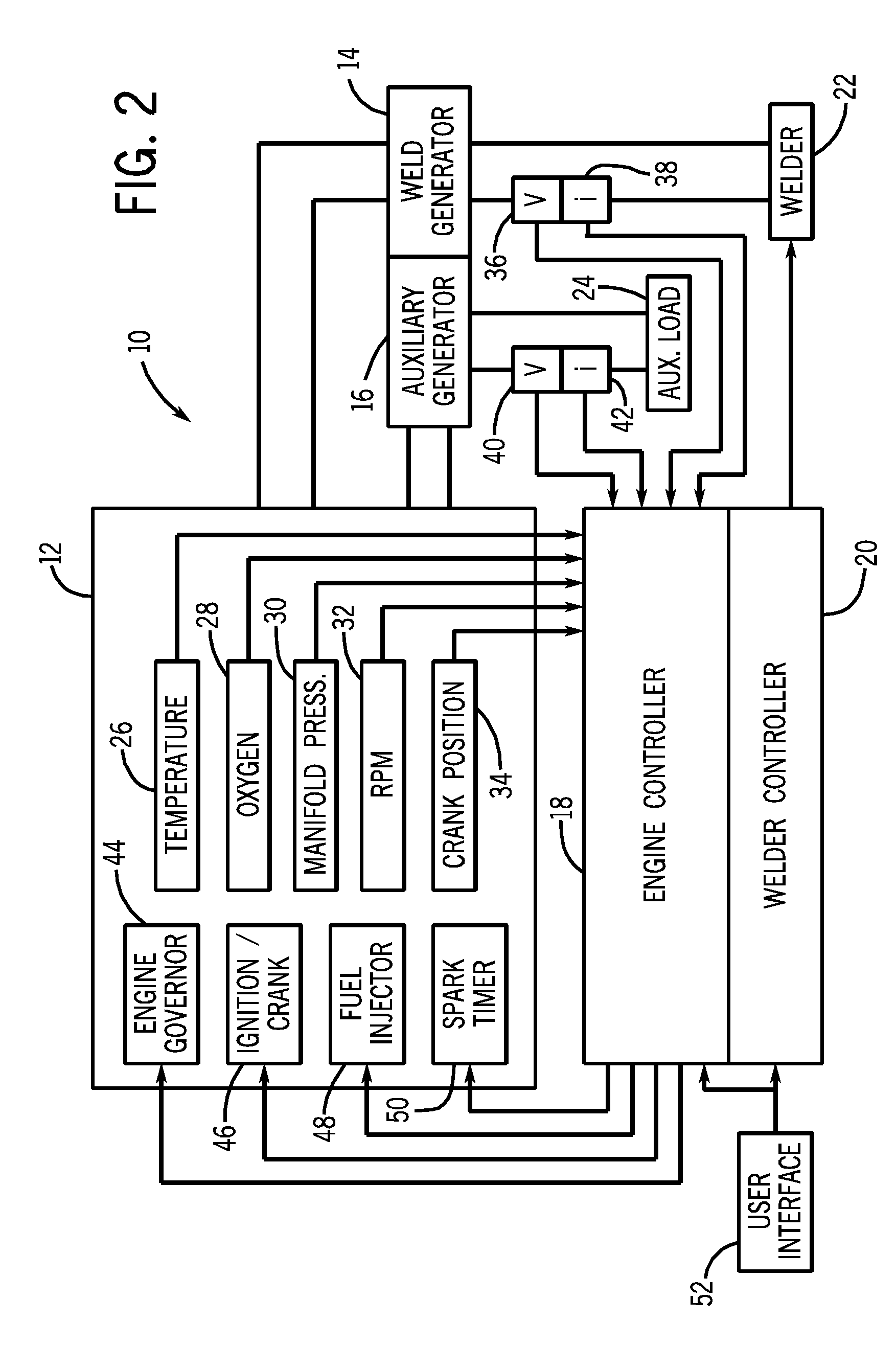
[0019]The present invention relates to control of an engine driving an electrical generator. An engine powering a generator / welder may include controls which affect the engine speed, ignition, fuel injection, spark timing, and any other controllable parameter of the engine based on various inputs. Such inputs may include, for example, currents or voltages supplied to loads, such as a welding gun and / or an auxiliary device, preset welding parameters, and time.

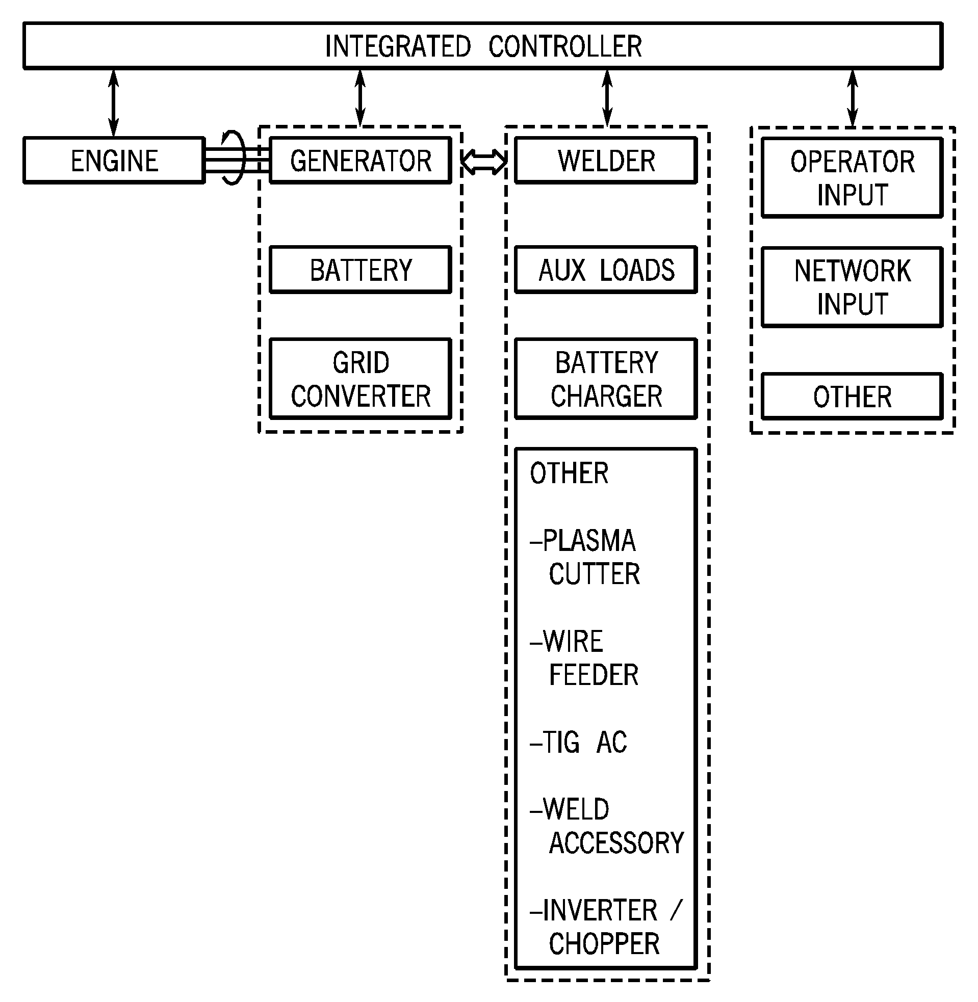
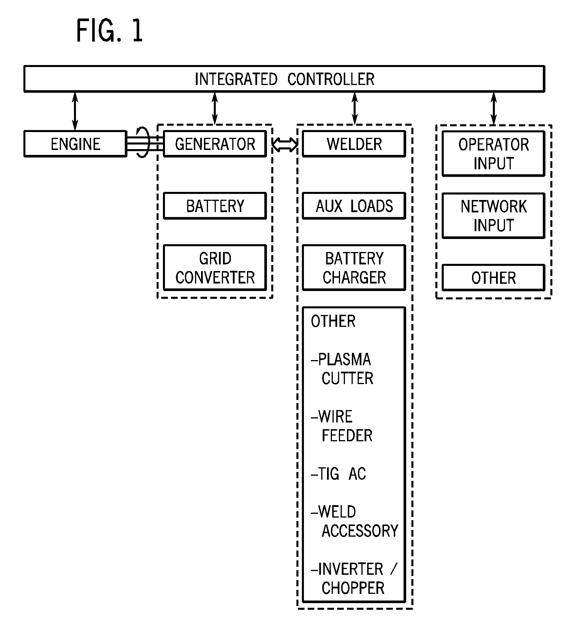
[0020]FIG. 1 is a diagrammatical overview of an exemplary integrated engine and generator control scheme in accordance with aspects of the present invention. As described in greater detail below, the system can be applied to a range of engines, such as gasoline engines and diesel engines. Moreover, the engine may include a wide range of measurable, observable and controllable parameters, such as, by way of example only, fuel flow, throttle position, speed, torque, power, spark advance (e.g., for gasoline engines), and so forth. ...


PUM

PropertyMeasurementUnit
frequenciesaaaaaaaaaa
frequencyaaaaaaaaaa
frequencyaaaaaaaaaa

Abstract

An engine-driven welder/generator is controlled by an integrated controller that is coupled to both the engine and to the welder/generator. The controller receives input signals for operational parameters of the engine, and additional signals indicative of electrical output by the welder/generator. Operation of the engine and welder/generator may thus be coordinated. The controller may control speed, timing, fuel injection, and so forth of the engine, and output of the welder/generator, such as by control of input to a field coil.

Description

BACKGROUND[0001]The invention relates generally to a system and method for controlling an engine driving a generator through the use of control circuitry that integrates control functions of both the engine and the generator.[0002]Engine-driven generators are commonly used to provide electrical power in locations where conventional electrical power is not readily available. Both gasoline and diesel engines are used to drive such generators, and the power produced is typically either 120 VAC or 240 VAC. An engine-driven generator may be used to supply power to a welding gun (e.g., torch, arc, or the like) for applications such as, for example, stick electrode welding, MIG welding, TIG welding, etc. These welding systems include a control system to regulate the power produced by the generator, thereby making it suitable for arc welding, plasma cutting, and similar operations.[0003]Typical welding systems offer the user little customizable control over the engine settings. For example,...

Claims


Application Information

Patent Timeline
Patent Type & Authority Applications(United States)
IPC IPC(8): B23K9/10
CPCB23K9/1056
Inventor BEESON, RICHARDFOSBINDER, DANIEL C.TRINKNER, MICHAEL J.
Owner ILLINOIS TOOL WORKS INC
Why Eureka
Try Eureka