Multiple voltage level driving for electrophoretic displays

a multi-voltage level, electrophoretic display technology, applied in the direction of electric digital data processing, instruments, computing, etc., can solve the problems of reducing grayscale resolution, limiting the number of grayscale outputs of the current driving method, and reducing the speed of the display driver ics and the display controller, so as to achieve better grayscale resolution and better control

Inactive Publication Date: 2010-08-05
SIPIX IMAGING INC
View PDF54 Cites 174 Cited by
  • Summary
  • Abstract
  • Description
  • Claims
  • Application Information

AI Technical Summary

Benefits of technology

[0007]The method can provide finer control over the driving waveforms and produce a better grayscale resolution.

Problems solved by technology

However, the driving methods currently available pose a restriction on the number of grayscale outputs.
This is due to the fact that display driver ICs and display controllers are limited in speed on the minimum pulse length that a waveform can have.
While current active matrix display architectures utilize ICs that can generate pulse lengths down to 8 msec leading to electrophoretic displays which have shortened response time, even below 150 msec, the grayscale resolution seems to diminish due to the incapability of the system to generate shorter pulse lengths.

Method used


Image

  • Multiple voltage level driving for electrophoretic displays
  • Multiple voltage level driving for electrophoretic displays
  • Multiple voltage level driving for electrophoretic displays

Examples


Embodiment Construction

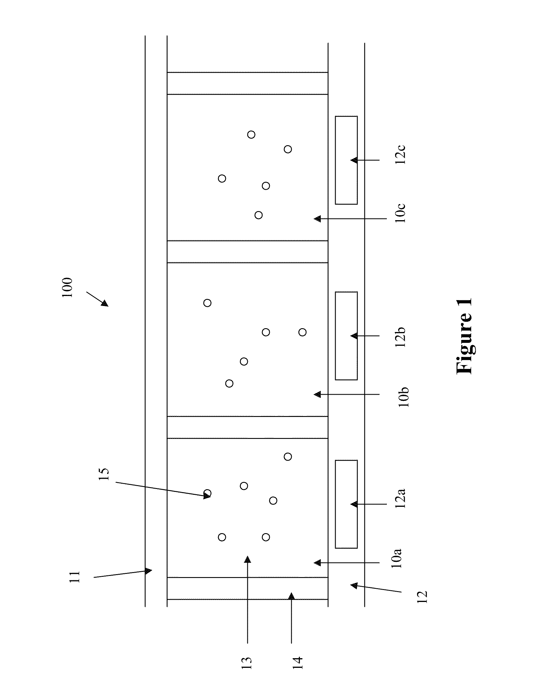
[0013]FIG. 1 illustrates a typical array of electrophoretic display cells 10a, 10b and 10c in a multi-pixel display 100 which may be driven by any of the driving methods presented herein. In FIG. 1, the electrophoretic display cells 10a, 10b, 10c, on the front viewing side, are provided with a common electrode 11 (which is usually transparent). On the opposing side (i.e., the rear side) of the electrophoretic display cells 10a, 10b and 10c, a substrate (12) includes discrete pixel electrodes 12a, 12b and 12c, respectively. Each of the pixel electrodes 12a, 12b and 12c defines an individual pixel of the multi-pixel electrophoretic display 100, in FIG. 1. However, in practice, a plurality of display cells (as a pixel) may be associated with one discrete pixel electrode. The pixel electrodes 12a, 12b, 12c may be segmented in nature rather than pixellated, defining regions of an image to be displayed rather than individual pixels. Therefore, while the term “pixel” or “pixels” is frequen...


PUM


Abstract

This application is directed to driving methods for electrophoretic displays. The driving methods comprise applying different voltages selected from multiple voltage levels, to pixel electrodes and optionally also to the common electrodes. In a preferred method, the different voltages are selected from a group consisting of 0V, at least two levels of positive voltage and at least two levels of negative voltage.

Description

[0001]The present application claims the benefit of U.S. Provisional Application 61 / 148,746, filed Jan. 30, 2009, which is incorporated herein by reference in its entirety.TECHNICAL FIELD[0002]The present invention relates to methods comprising applying a voltage selected from multiple voltage levels to drive an electrophoretic display.BACKGROUND OF THE INVENTION[0003]An electrophoretic display (EPD) is a non-emissive device based on the electrophoresis phenomenon of charged pigment particles suspended in a solvent. The display usually comprises two plates with electrodes placed opposing each other. One of the electrodes is usually transparent. A suspension composed of a colored solvent and charged pigment particles is enclosed between the two plates. When a voltage difference is imposed between the two electrodes, the pigment particles migrate to one side or the other, according to the polarity of the voltage difference. As a result, either the color of the pigment particles or the...

Claims


Application Information

Patent Timeline
Patent Type & Authority Applications(United States)
IPC IPC(8): G06F3/038G09G3/34
CPCG09G2330/028G09G3/344
Inventor LIN, CRAIGPHAM, TINPERI, MANASACHAN, BRYAN
Owner SIPIX IMAGING INC
Why Eureka
Try Eureka