
Eureka
For R&D, Eureka makes reading and utilizing patents & technical documents easy.
Eureka AIR
Designed for self-driven R&D workflows. Generate viable solutions, solve complex R&D challenges, empower your innovation with AI.

Eureka Materials
Designed for material experts only. Revolutionize your material R&D, from search, analyze, to developing new materials.

TechResearch
Generate reliable direction feasibility study reports for your R&D in just a few steps.

TechSeek
Discover and master advanced knowledge NOW. Basics, ideas, possibilities, all at once.

TechMind
As an expert in R&D Theories, TechMind can generates customized viable solutions instantly.

TechRisk
Analyze your overall solution with one click, know your potential R&D risks in advance.

TechMonitor
Get weekly tech updates, stay abreast of the latest tech innovations and key insights.
Liquid ejection head, ink cartridge, and image forming apparatus
- Summary
- Abstract
- Description
- Claims
- Application Information
AI Technical Summary
Benefits of technology
Problems solved by technology
Method used
Image

Examples
first embodiment
[0066]Referring to FIGS. 6 through 8, the present invention is described. Note that FIG. 6 is an explanatory view of the FPC 15, FIG. 7 is a perspective explanatory view of the actuator unit 100 of the head having the FPCs 15 mounted thereon, and FIG. 8 is a perspective explanatory view of the head having a wiring board mounted thereon as seen from the side opposite to a nozzle surface.
[0067]As shown in FIG. 6, the driving IC 16 is mounted on the FPC 15 for selectively applying driving waveforms to the driving piezoelectric element columns 12A of the piezoelectric elements 12 as the driving elements 12A. The number of wirings is increased as the number of nozzles increases. If the driving IC 16 is mounted on a controlling part for an apparatus main body (hereinafter referred to as a “main body controlling part”) or a relay board connected to the main body controlling part, it becomes difficult to realize packaging for connecting the driving elements 12A (driving piezoelectric elemen...
second embodiment
[0075]Referring to FIG. 9, a description is now made of the present invention. Note that FIG. 9 is a perspective explanatory view for explaining this embodiment.
[0076]In this embodiment, an electrostatic actuator unit 101 having two driving element rows in which plural rows of electrostatic actuators as driving elements are arranged side by side is arranged on a base member 102, and two sheets of the FPCs 15 are provided to correspond to the driving element rows of the electrostatic actuator unit 101.
[0077]In this case, the two sheets of the FPCs 15 are arranged facing each other in such a manner as to be folded and arranged one adjacent to each side surface of the base member 102. That is, the FPCs “arranged facing each other” in the present invention refer to those that are folded to have facing surfaces (opposite surfaces) although they do not face each other at their parts connected to the driving elements.
third embodiment
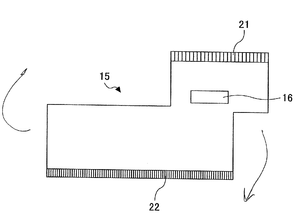
[0078]Referring to FIGS. 10 through 14, a description is now made of the present invention. Note that FIG. 10 is an explanatory view of the FPC 15, FIG. 11 is an explanatory view for explaining how to extract the FPCs 15, FIG. 12 is a schematic explanatory perspective view of a head according to this embodiment, FIG. 13 is a perspective explanatory view of an actuator unit of the head having the FPCs 15 mounted thereon, and FIG. 14 is a perspective explanatory view of the head having a wiring board mounted thereon as seen from the side opposite to a nozzle surface.
[0079]Here, as shown in FIG. 10, the FPC 15 is so arranged that the length “L1” of the input terminal part 21 is half or less of the length “L2” of the output terminal part 22, the input terminal part 21 is formed in a position biased from the center to the end of the output terminal end 22, and the end “E1” of the input terminal part 21 is positioned so as not to be outside of the end “E2” of the output terminal part 22.
[...
PUM
 Abstract
Description
Claims
Application Information
 - R&D Engineer
- R&D Manager
- IP Professional
- Industry Leading Data Capabilities
- Powerful AI technology
- Patent DNA Extraction
Browse by: Latest US Patents, China's latest patents, Technical Efficacy Thesaurus, Application Domain, Technology Topic, Popular Technical Reports.
© 2024 PatSnap. All rights reserved.Legal|Privacy policy|Modern Slavery Act Transparency Statement|Sitemap|About US| Contact US: help@patsnap.com