Eyepiece base unit and microscope

a microscope and base unit technology, applied in the field of microscopes, can solve the problem of inability to perform external phase contrast observation, and achieve the effect of easy addition to the microscop

Active Publication Date: 2010-08-05
NIKON CORP
View PDF5 Cites 6 Cited by
  • Summary
  • Abstract
  • Description
  • Claims
  • Application Information

AI Technical Summary

Benefits of technology

[0008]According to the present invention, the function of external ph

Problems solved by technology

However if a microscope which the user has already purchased is a microscope with which phase contrast observation cannot be performed, the external

Method used


Image

  • Eyepiece base unit and microscope
  • Eyepiece base unit and microscope
  • Eyepiece base unit and microscope

Examples


Embodiment Construction

[0045]Embodiments of the present invention will now be described with reference to the drawings.

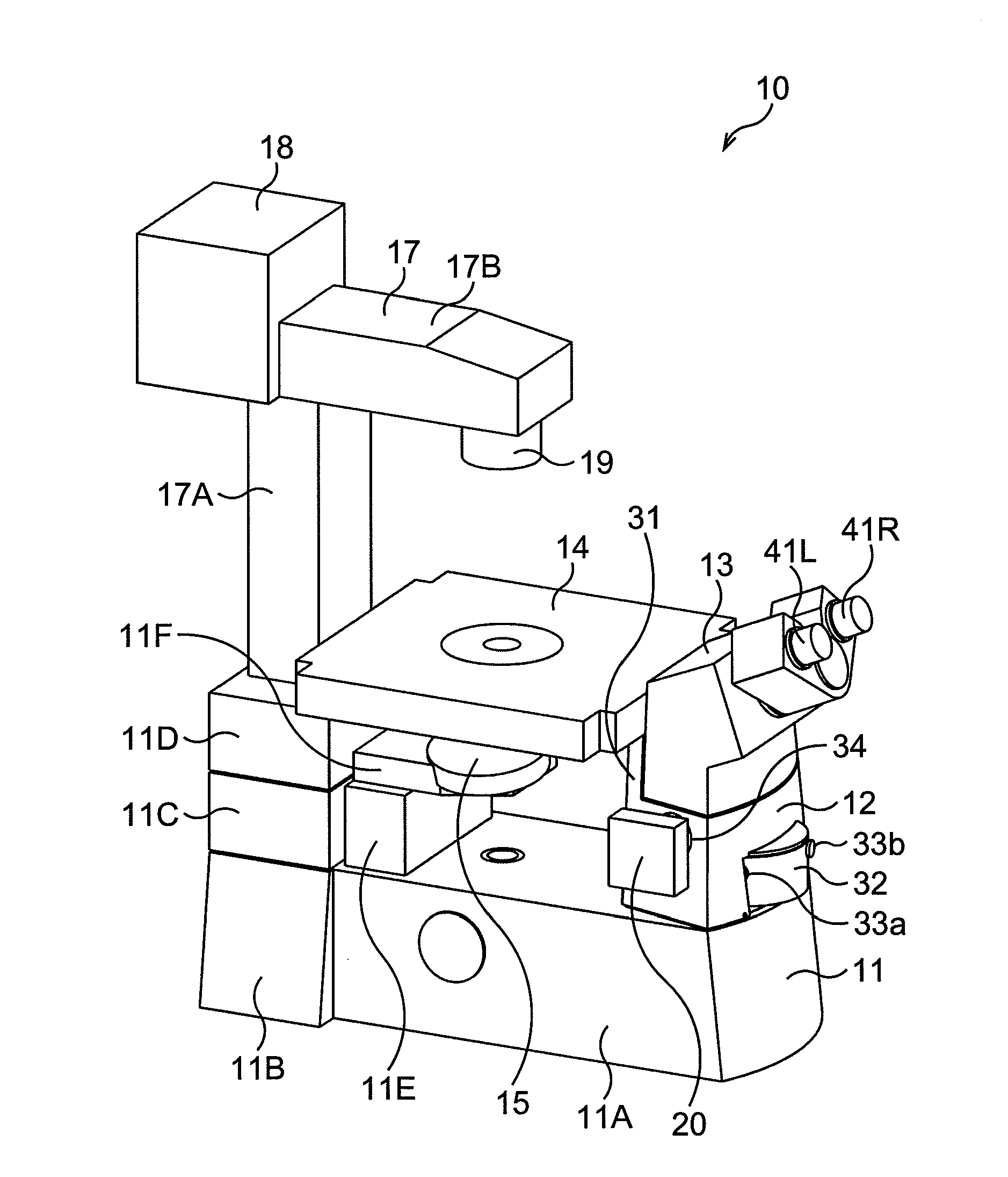
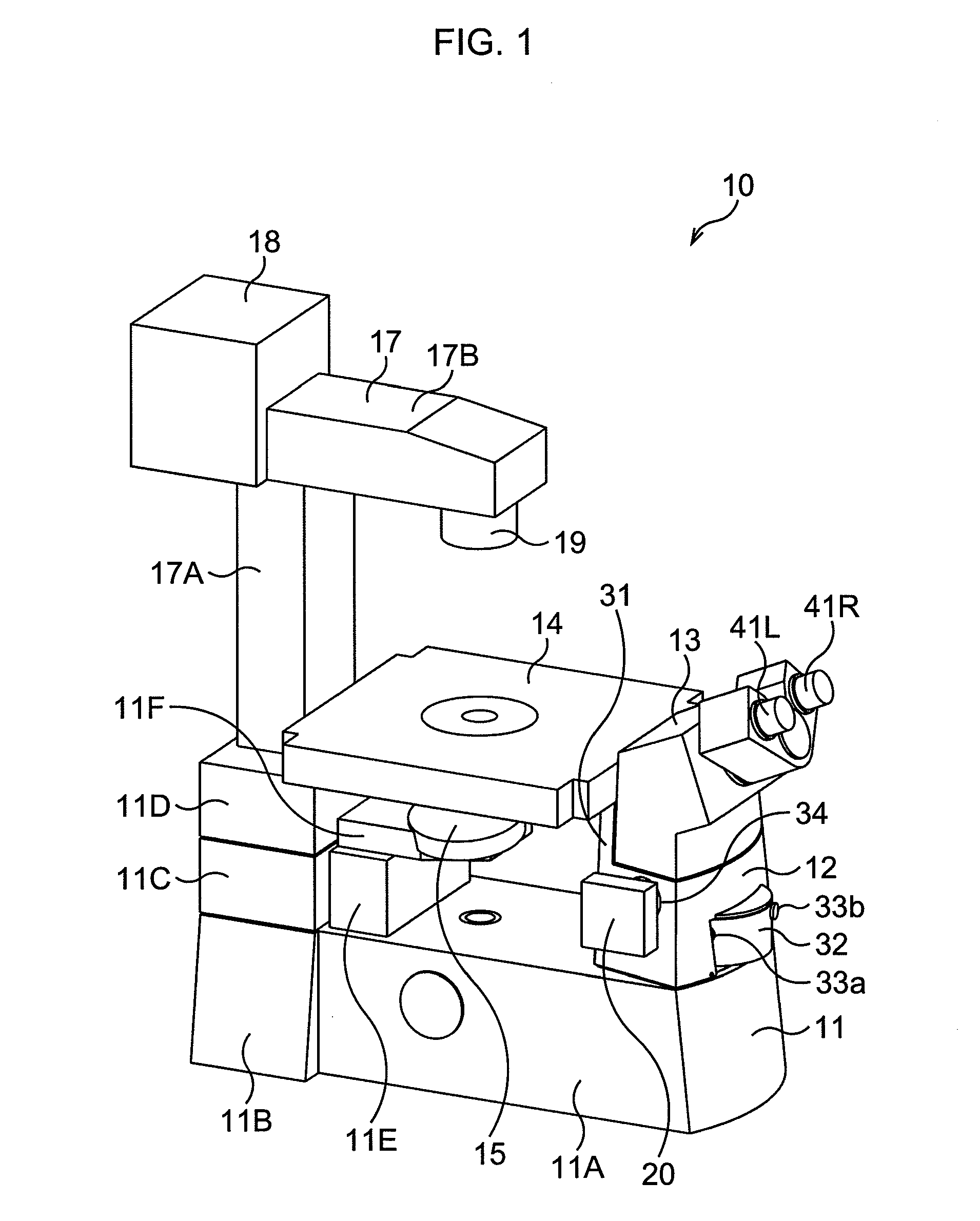
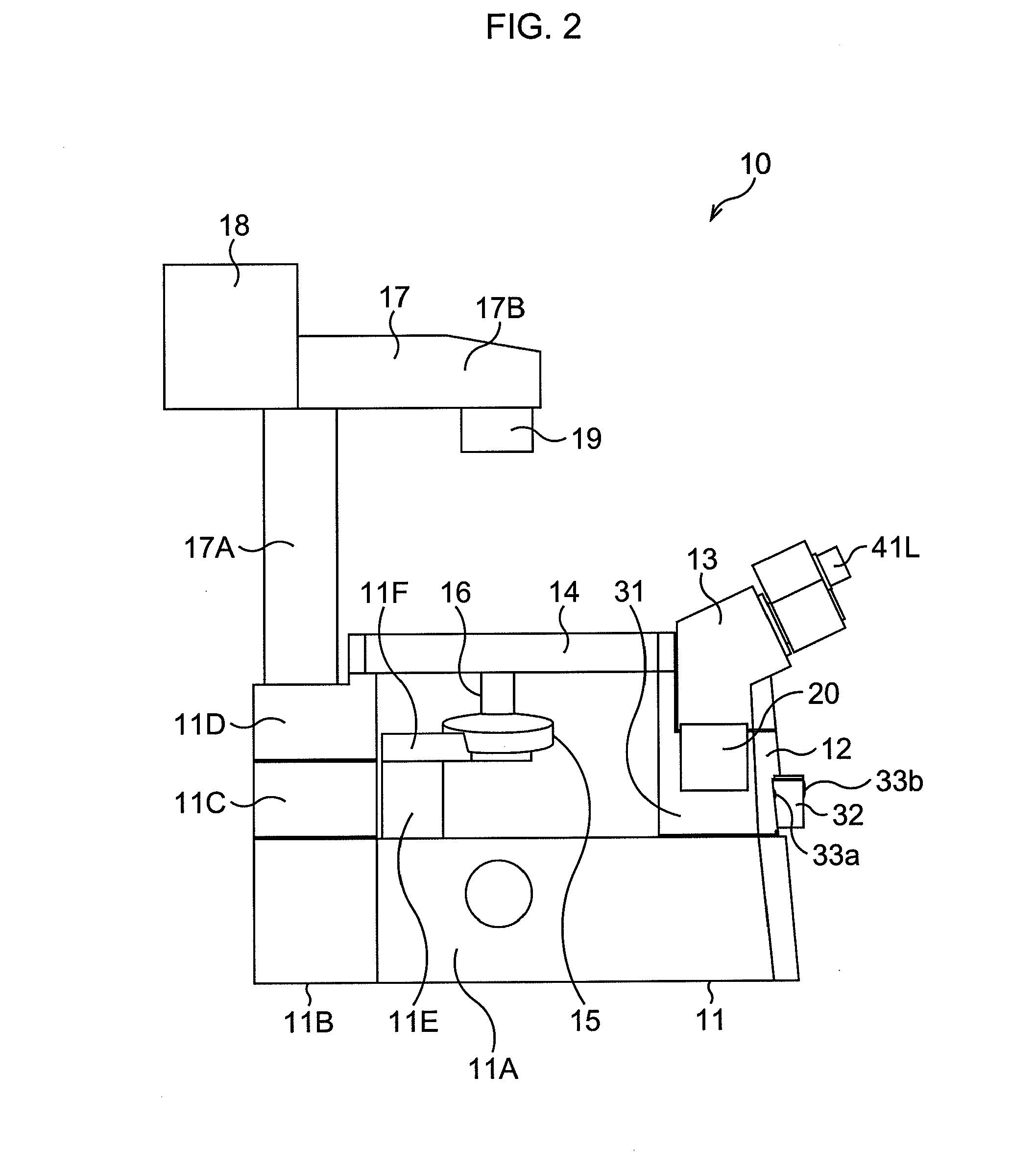
[0046]FIG. 1 and FIG. 2 are external views of one embodiment of a microscope to which the present invention is applied. FIG. 1 is a perspective view of the microscope 10, and FIG. 2 is a side view of the microscope 10.

[0047]In the microscope 10, the side of the user looking into the microscope 10 via the eyepiece tube 13 when the microscope 10 is used (right side in FIG. 1 and FIG. 2) is called the “user side” herein below. Also in the microscope 10, it is assumed that the front direction is the user side, the rear direction is the opposite side of the user side, the left direction is the left side as the user faces the microscope 10, and the right direction is the right side as the user faces the microscope 10.

[0048]The main unit 11 is comprised of units 11A to 11F. An eyepiece base unit 12 is disposed in the front end of the top face of the unit 11A, and the unit 11E is disposed in the ...


PUM


Abstract

The present invention relates to an eyepiece base unit and a microscope with which a phase contrast observation function can be easily added to the microscope.
The eyepiece base unit 12 is removably attached to a main unit of the microscope, and includes, in a state of being attached to the microscope, a pupil conjugate plane, which is a plane conjugate with an image side focal plane of an objective lens in an observation optical system of the microscope. By rotating a turret 32 around a central axis 67, phase plates 64a and 64c installed in the turret 32 can be inserted into the pupil conjugate plane. The present invention can be applied to a phase contrast microscope, for example.

Description

TECHNICAL FIELD[0001]The present invention relates to an eyepiece base unit and a microscope, and more particularly to an eyepiece base unit and a microscope to which an external phase contrast observation function can be easily added.BACKGROUND ART[0002]A type of conventional optical microscope is a phase contrast microscope which supports phase contrast observation of a sample, and another so called external phase contrast microscope is known, in which a phase plate used for phase contrast observation is installed on a pupil conjugate plane, that is, a plane conjugate with an image side focal plane of the objective lens (also called “pupil plane” herein below) in order to perform phase contrast observation without dropping the NA of the objective lens. Patent Document 1 discloses that phase plates are installed on a slider that enables the phase plates to be inserted into / removed from the optical path, so that a suitable phase plate is disposed on the optical path according to the...

Claims


Application Information

Patent Timeline
IPC IPC(8): G02B21/24
CPCG02B21/0088G02B21/24G02B21/14
Inventor TAMURA, MASAAKI
Owner NIKON CORP
Why Eureka
Try Eureka