Apparatus, method, and system for highly controlled light distribution using multiple light sources

a technology of light source and light source, applied in the field of lighting systems and methods, can solve the problems of inability to adapt to the application, the design of optics is only useful, and the fixture affords little flexibility, so as to facilitate customization in lighting and achieve greater control over light distribution and light intensity

Active Publication Date: 2010-08-05
MUSCO
View PDF67 Cites 57 Cited by
  • Summary
  • Abstract
  • Description
  • Claims
  • Application Information

AI Technical Summary

Benefits of technology

[0007]Envisioned are apparatus, method, and system for lighting fixtures which comprise adjustable components to facilitate customization in lighting a target area in a manner that allows greater control over light distribution and light intensity than in some fixtures in the current state of the art. Embodiments of the present invention are described with reference to LEDs and LED lighting, however, embodiments of the present invention are equally applicable to other solid state light sources, other lighting devices (e.g., lasers), or other fixtures that allow for multiple light sources to be packaged together in a small area.

Problems solved by technology

One disadvantage to such current art approaches is that the designed optics are only useful in producing a single beam type; they must be modified or replaced if a different beam type is desired.
Additionally, such fixtures afford little flexibility; a type II beam pattern (as defined by IES) may be sufficient to illuminate a target area but if the target area changes (e.g., the area to be illuminated is increased, the target area is moved), or the lighting needs change (e.g., spill light needs to be eliminated, glare needs to be controlled), the beam type may no longer be appropriate for the application.

Method used


Image

  • Apparatus, method, and system for highly controlled light distribution using multiple light sources
  • Apparatus, method, and system for highly controlled light distribution using multiple light sources
  • Apparatus, method, and system for highly controlled light distribution using multiple light sources

Examples


embodiment i

[0036]B. Exemplary Method and Apparatus Embodiment I

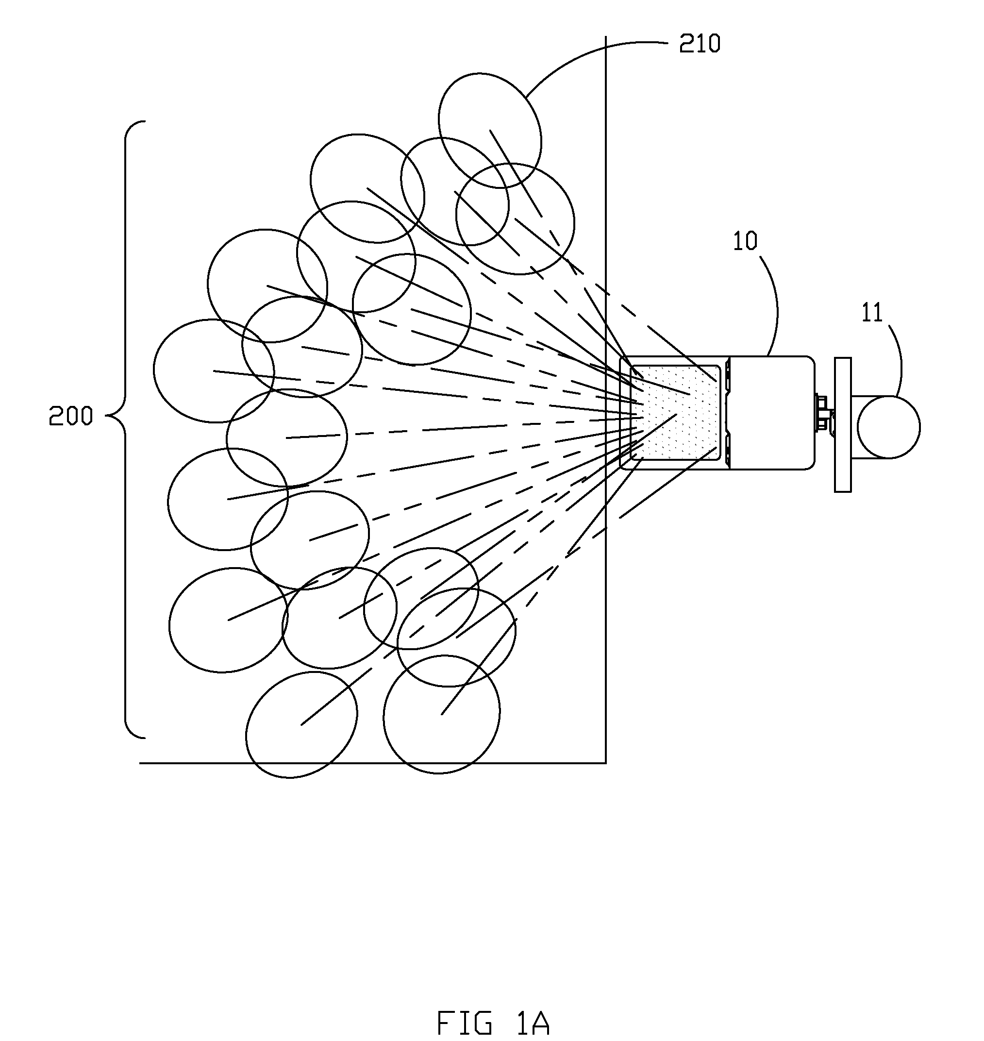
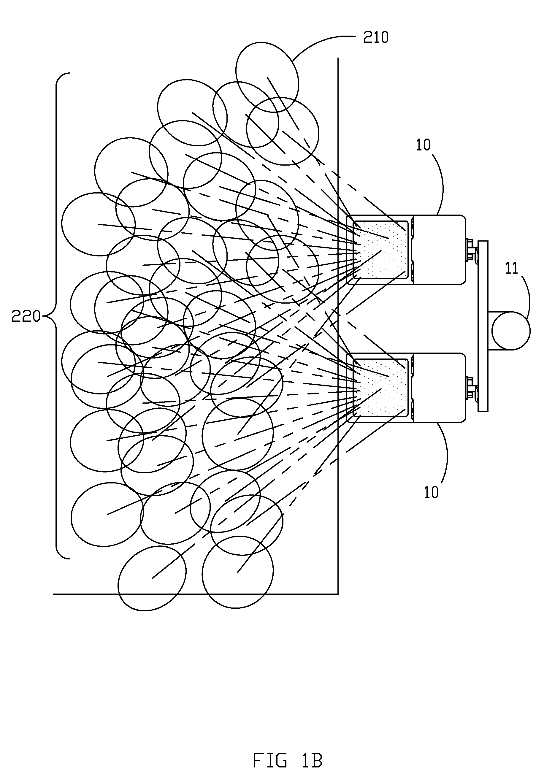
[0037]A more specific exemplary embodiment, utilizing aspects of the generalized example described above, will now be described. FIG. 2 illustrates one possible lighting fixture 10 which houses multiple LEDs and comprises an aluminum housing 14, a removable panel 13 for access to the power regulating devices associated with the LEDs (which are well known in the art of lighting), a removable lens 15 for access to the LEDs and associated optics, and an adjustable mounting knuckle 12 for mounting lighting fixture 10 to a pole 11 or other structure. As described in the incorporated-by-reference parent patent applications, lens 15 may further comprise an anti-reflective coating which, as is well known in the art of lighting, may allow for a variety of angles of incidence up from normal.

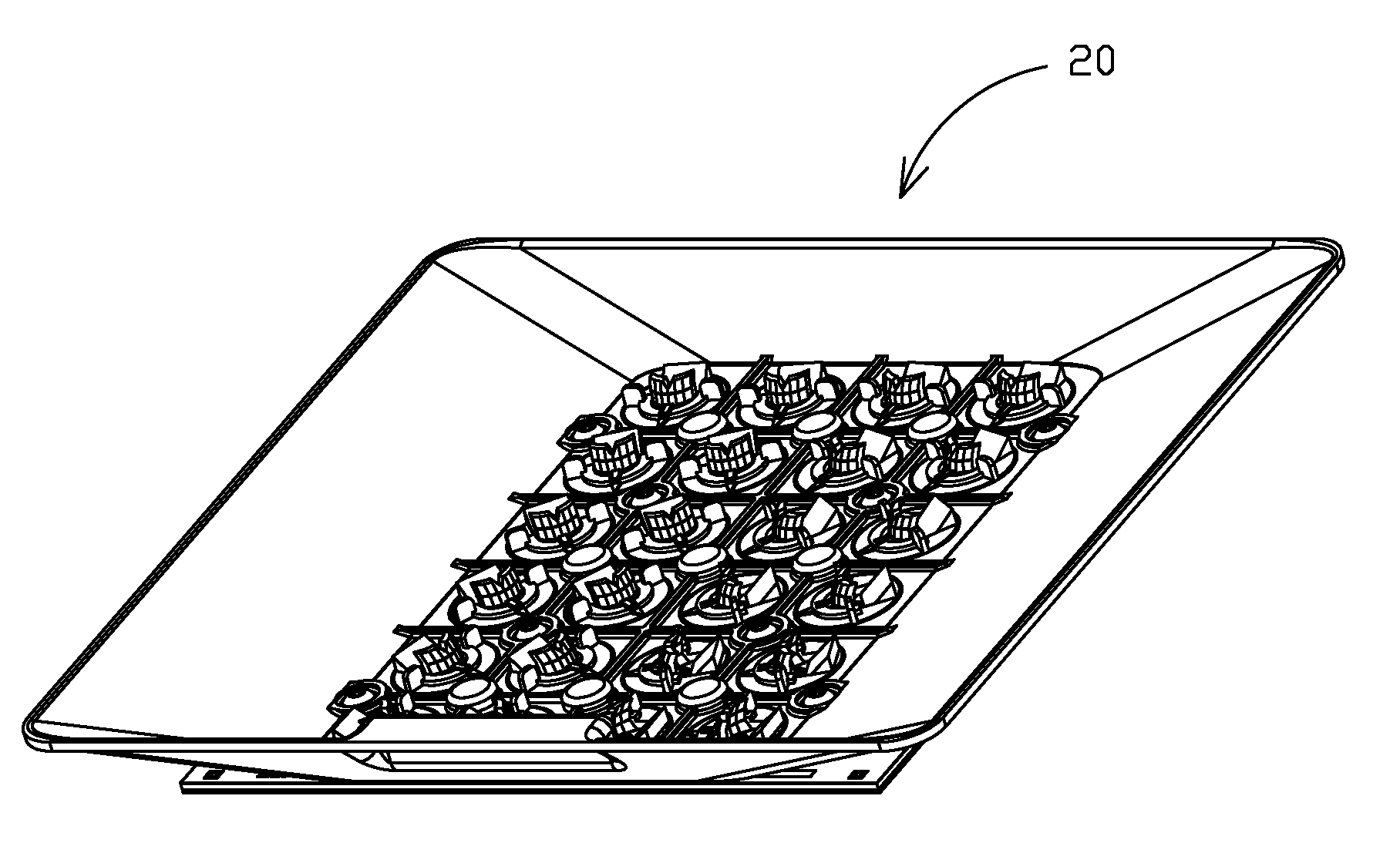
[0038]FIGS. 3A-C illustrate a subassembly 20 housed in fixture 10 which comprises a thermal interface layer 27, LED circuit board 21, LEDs 22, locating r...


PUM


Abstract

Disclosed herein are apparatus, method, and system for producing a customizable composite beam from a plurality of solid state light sources. Each light source is associated with individually adjustable fixture components which allow for a variety of lighting needs to be addressed. The composite beam is a collective of the beam projected from each adjustable component/light source combination; each individual beam being of customized shape or standard shape.

Description

CROSS-REFERENCE TO RELATED APPLICATIONS[0001]This application is a continuation-in-part of co-pending PCT application No. PCT / US09 / 57090 filed Sep. 16, 2009, and co-pending U.S. Ser. No. 12 / 467,160 filed May 18, 2009, both of which claim priority to provisional U.S. Ser. No. 61 / 097,483 filed Sep. 16, 2008, which are hereby incorporated by reference in their entirety.BACKGROUND OF THE INVENTION[0002]The present invention generally relates to systems and methods for lighting. More specifically, the present invention relates to an adjustable lighting fixture utilizing light emitting diodes (LEDs) to produce highly controlled and highly customized lighting.[0003]In the current state of the art, the light projected from a fixture is often characterized in terms of the pattern of light as viewed on a target area; this is often referred to as the beam distribution type, beam type, or beam pattern. Beam distribution types are well known in the state of the art and are well defined and stand...

Claims


Application Information

Patent Timeline
Patent Type & Authority Applications(United States)
IPC IPC(8): F21V1/00F21S8/00
CPCF21K9/00F21V7/0066F21V7/0083F21V7/09F21V14/04F21V17/02F21V19/001F21V21/30F21V29/004F21W2131/103F21W2131/105F21W2131/107F21Y2101/02F21Y2105/001G02B19/0066G02B19/0023G02B19/0028F21V7/0025F21S8/08F21Y2105/10F21Y2115/10F21K9/68F21V29/507
Inventor BOXLER, LAWRENCE H.LICKISS, CHRIS P.MCKEE, LUKE C.
Owner MUSCO
Why Eureka
Try Eureka