Heterodyned Seismic Source

a seismic source and heterodyne technology, applied in seismology, seismicology, instruments, etc., can solve the problems of affecting marine life, physical and/or behavioral changes of these animals, and unable to provide a method to obtain geologically relevant frequencies from 0-200 hz, so as to eliminate the harmful effects of seismic surveys

Inactive Publication Date: 2010-08-05
CONOCOPHILLIPS CO
View PDF22 Cites 31 Cited by
  • Summary
  • Abstract
  • Description
  • Claims
  • Application Information

AI Technical Summary

Benefits of technology

[0009]The present invention eliminates the harmful effects of seismic surveys by using heterodyned signals that individually are outside frequencies relevant to marine life, but when heterodyned provide a controlled seismic energy source. Because the seismic energy is directional and encoded, the heterodyned signal provides a unique, localized signal for seismic surveys. By using a constant frequency carrier from one transmitter while a second transmitter sweeps a slightly different, changing frequency, amplitude or phase around the carrier, the combination of two frequencies leaves a unique seismic signal at a mathematically defined location.
[0016]The transducer can be an electronic controller connected to one or more marine piezoelectric transducers. In one example, piezoelectric transducers with resonant frequencies of approximately 12 KHz can be used to provide a steady resonant frequency signal of 12, 24, 28, and / or 33 KHz. The encoded transducer is the same transducer as previously described but generates encoded frequencies above and below the resonant frequency of the carrier transducer. The transducers may be piezoelectric, but other transducers may be used including marine hydraulically actuated transducers. To further reduce the effects of stray ultrasonic and / or heterodyned seismic signals, transducers can be arrayed within a resonant chamber with sound dampening material on all external surfaces except for the downward-facing surface.

Problems solved by technology

The impact of human-made sounds may potentially result in physical and / or behavioral changes for these animals.
Although specific seismic signals are used, they do not provide a method to obtain geologically relevant frequencies from 0-200 Hz and exclude overlapping frequencies used by sensitive marine life.
Shear waves and acoustic waveforms produced by these marine seismic sources such as air guns and hydraulic or “flextensional” acoustic actuators are at frequencies that may be harmful to marine life.
These sources may not be used during periods of animal activity, near sensitive ecosystems, or may be limited by other factors.
Cetaceans have been observed avoiding powerful, low frequency sound sources and there now may be a documented case of injury to whales from multiple, mid frequency (2.6-8.2 kHz) military echo sounders.
In the case of other animals, evidence of short term displacement suggests some seals and fish are affected by seismic surveys but there is little literature available (Australian Government, EPBC Act Policy Statement).
The cessation of seismic surveys for the protection of marine biota interferes with contiguous data segments, slows data acquisition, delays projects, and increases costs exponentially.
In some cases, data is never acquired and prospective regions are either poorly imaged or not imaged at all.

Method used


Image

  • Heterodyned Seismic Source
  • Heterodyned Seismic Source
  • Heterodyned Seismic Source

Examples


example 1

Heterodyned Beam

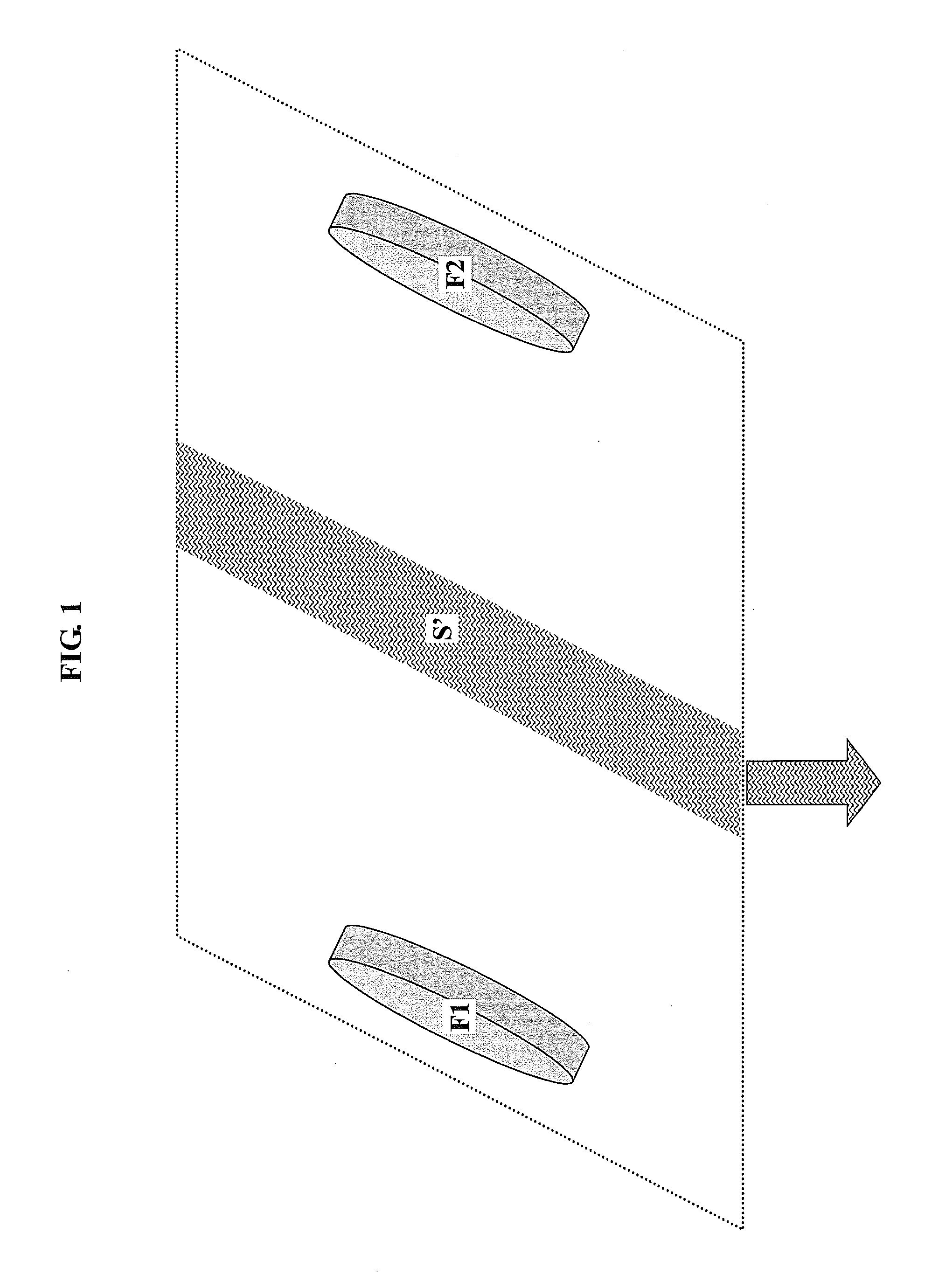
[0027]A simple array of two piezo transducers S1 and S2, with simple sine-wave signals f1 and f2 respectively. By placing S1 and S2 near each other, a set of beams is created where the two signals interfere. The resulting signal is composed of:

S′(t)=½ cos [(2π)*(f1+f2)*t]+½ cos [(2π)*(f1−f2)*t]

[0028]The signal is defined such that f1 is the first or baseline frequency, f2 is the modulating frequency, and t is time. Assuming a significant fraction of energy is propagated into the media, then the difference frequency (f1−f2) will be propagated wherever the interference beams exist. If f1 and f2 are on the order of 20 KHz, then marine life will not be affected by f1 or f2, but if they differ by 1-80 Hz, then a seismically interesting “beat” frequency will be transmitted along the beams. Thus a sweep of 1 to 80 Hz could be created by modulating f2 as a function of t.

[0029]By varying the arrays and sweeps, a very narrow, directional, and controlled beam of seismic source ...

example 2

Two Transducer Beam

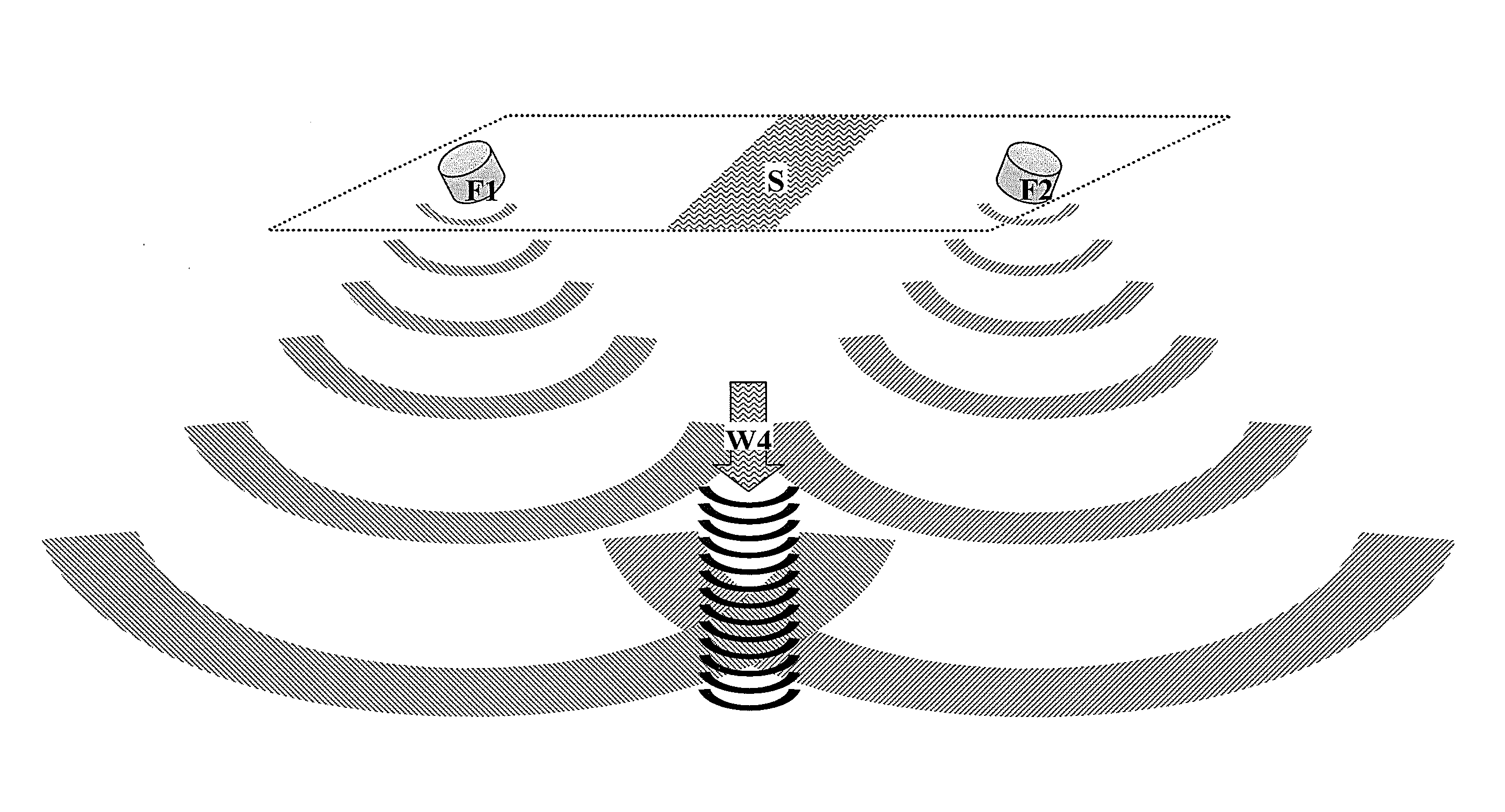
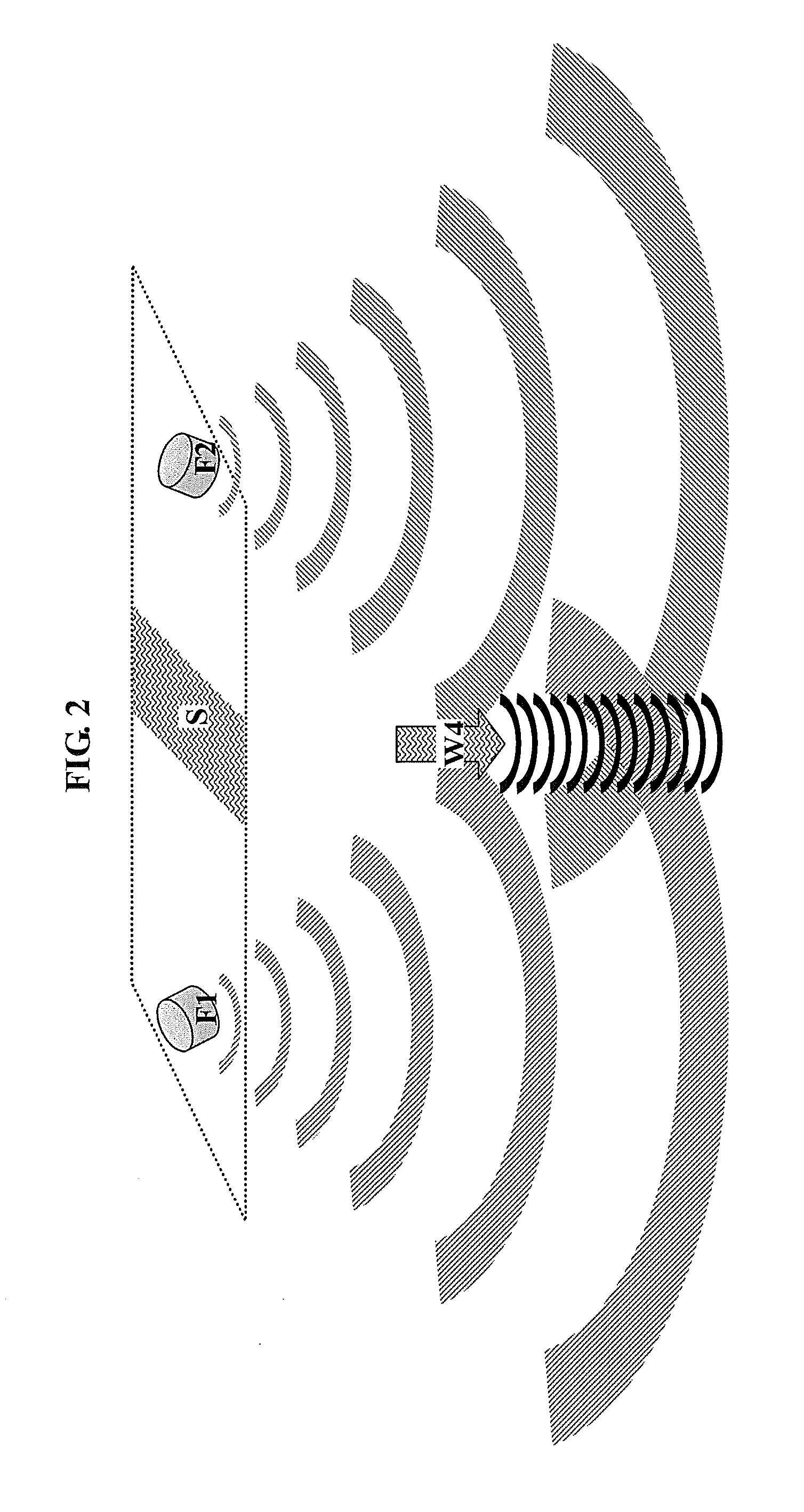
[0030]As shown in FIG. 2, a side view of two transducers (f1 and f2) wherein f1 transmits a high frequency vibrational signal and f2 transmits a slightly different high frequency vibrational signal.

f1=A sin(w1t)

f2=A sin(w2t)

[0031]Due to interference, an encoded heterodyne signal is generated at the sea floor while signals in the water are well above frequencies that disturb sea life. Because these signals are generated without injuring the sensitive marine environment, the heterodyne signal can replace air-gun arrays in environmentally-sensitive areas. This allows seismic surveys in areas where governments have blocked access for seismic surveys.

example 3

Airmar Piezoelectric

[0032]As discussed in Example 2, a test apparatus is constructed using two AIRMAR M187 transducers in a tank of sea water with sound absorbing materials on the sides and bottom. Using an array of pressure sensors across the sides and bottom of the tank, energy levels and beam patterns are measured as the frequency of one of the sources is varied above and below the resonant frequency chosen for the carrier of the other source. These tests determine the relative amount of energy that can effectively be transmitted within the range required for seismic work.


PUM


Abstract

The invention relates to an apparatus for generating heterodyned seismic signals as well as methods of using the heterodyned signals and a system for generating the heterodyned seismic signals. The heterodyned signals can be used near sensitive marine animals because the source frequencies are ultrasonic and the heterodyned seismic signal is generated in a narrow beam.

Description

CROSS-REFERENCE TO RELATED APPLICATIONS[0001]This application is a non-provisional application which claims benefit under 35 USC §119(e) to U.S. Provisional Application Ser. No. 61 / 148,522 filed Jan. 30, 2009, entitled “Heterodyned Seismic Source,” which is incorporated herein in its entirety.STATEMENT REGARDING FEDERALLY SPONSORED RESEARCH OR DEVELOPMENT[0002]None.FIELD OF THE INVENTION[0003]The present disclosure generally relates to methods and apparatus for generating a heterodyned seismic signal. In one embodiment a defined beam of heterodyned signal is formed. A heterodyned signal is less harmful to marine life since it does not direct broad-band energy into the surrounding ocean, and it is highly controllable, enabling encoded source signature information.BACKGROUND OF THE INVENTION[0004]In order to assess the location and size of potential hydrocarbon reservoirs, marine seismic sources typically use arrays of air guns to provide enough signal to penetrate sedimentary and sal...

Claims


Application Information

Patent Timeline
Patent Type & Authority Applications(United States)
IPC IPC(8): G01V1/38
CPCG01V1/005
Inventor MENGER, WILLIAM M.BREWER, JOEL D.EICK, PETER M.
Owner CONOCOPHILLIPS CO
Why Eureka
Try Eureka