
Interface monitoring for link aggregation

a technology of interface monitoring and link aggregation, applied in the field of computer network topologies, can solve problems such as serious network communication problems, degrade or prevent communication among devices on the network, and cannot be used in an active/standby link aggregation mod

Active Publication Date: 2010-08-05
GOOGLE LLC
View PDF11 Cites 126 Cited by
  • Summary
  • Abstract
  • Description
  • Claims
  • Application Information

AI Technical Summary

Benefits of technology

[0008]In accordance with aspects of the present invention, robust inter...

Problems solved by technology

A link failure may degrade or prevent communication among devices on the network.
This can be a serious problem in network communication.
One limitation on this technique is that it relies on the “liveness” of designated peers.
Another limitation is that it may not be used in an active / standby link aggregation mode.
It does not detect interface failure when the carrier state is up but the link is down due to bad cables or other issues.

Method used


Image

  • Interface monitoring for link aggregation
  • Interface monitoring for link aggregation
  • Interface monitoring for link aggregation

Examples


Embodiment Construction

[0026]The aspects, features and advantages of the present invention will be appreciated when considered with reference to the following description of preferred embodiments and accompanying figures. The following description does not limit the present invention; rather, the scope of the invention is defined by the appended claims and equivalents.

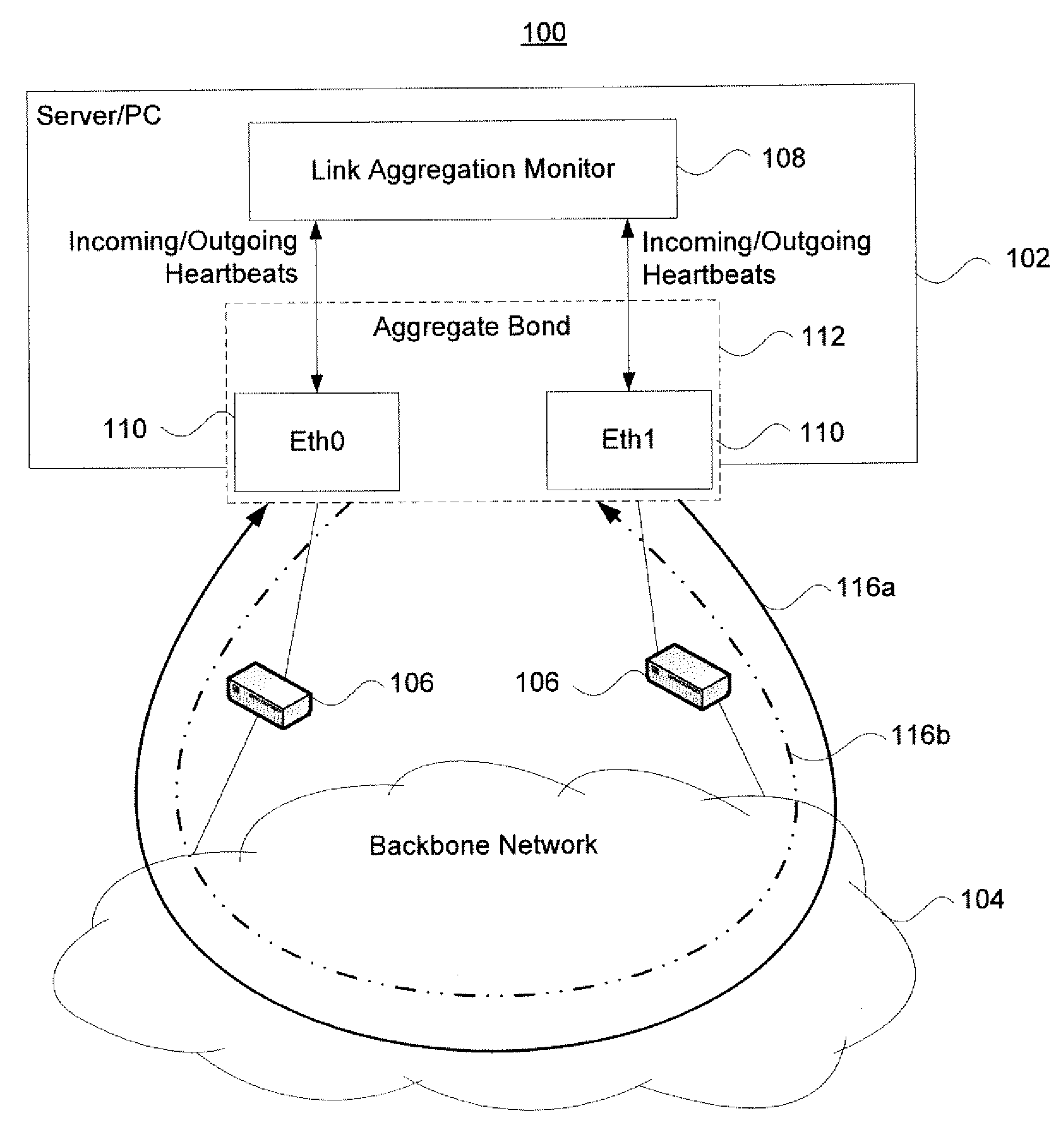
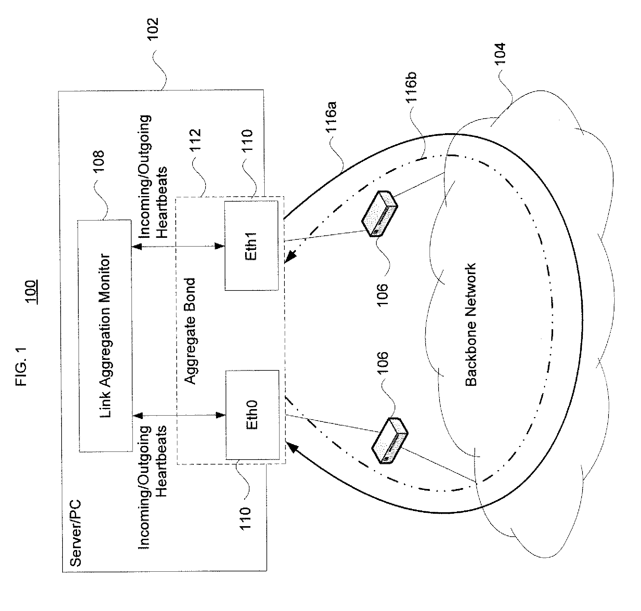
[0027]FIG. 1 illustrates a system 100 that implements link aggregation monitoring in accordance with aspects of the present invention. The system 100 includes a host device 102, a backbone network 104, and internetworking devices 106 such as routers, hubs, bridges or switches. The host device 102 may comprise a server, PC, network switch etc. In one example, the host device 102 may be a switch used in a network datacenter. As shown, the host device 102 is coupled to the backbone network 104 via the internetworking devices 106.

[0028]The host device 102 includes a link aggregation monitor 108 and a pair of network interfaces 110 identified as ...


PUM


Abstract

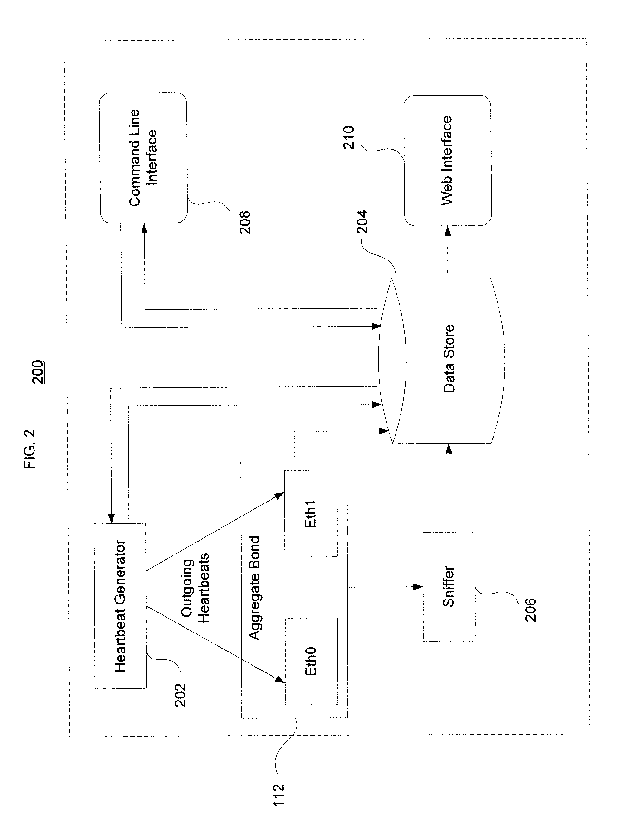
The present invention provides network interface monitoring and management that may be employed with link aggregation technologies. Multiple network interfaces may be aggregated into a single bond and data may be transferred to and from a backbone network via this aggregated bond. A link aggregation monitor employs a heartbeat generator, sniffer and data store to keep track of health and availability of network interfaces. The heartbeat generator sends heartbeats to the network interfaces, which pass the heartbeats around in a token ring configuration. If a network interface fails or otherwise goes offline, detection of this condition causes the monitor and heartbeat generator to prepare new or modified heartbeats so that data may be efficiently and accurately routed around the token ring and health of all remaining alive interfaces can be monitored properly. If a network interface re-enters or is added to the aggregate bond, new / modified heartbeats are then employed.

Description

BACKGROUND OF THE INVENTION[0001]1. Field of the Invention[0002]The invention relates generally to computer network topologies. More particularly, the invention pertains to link aggregation interface monitoring.[0003]2. Description of Related Art[0004]On a networked machine, it is possible to increase the communication bandwidth or the availability of network connectivity, by using multiple interfaces concurrently. This is known as “link aggregation.” Link aggregation technologies enable the machine deployed with multiple network interfaces, called “slaves,” to aggregate the bandwidth of multiple interfaces, or to maintain network connectivity despite interface failures. In particular, existing link aggregation technologies support two modes of operations: load balancing or active / standby mode. Load balancing mode requires the router(s) / switch(es) (connected to the networked machine) to support link aggregation technologies as well. In load balancing mode, the networked machine uses...

Claims


Application Information

Patent Timeline
IPC IPC(8): H04L12/24H04L12/26H04L45/243H04L45/28
CPCH04L12/433H04L43/0817H04L43/10H04L45/28H04L45/245Y02B60/33H04L43/106Y02D30/50
Inventor ZHOU, JUNLANJI, ZHENGRONGWU, YUGUANG
Owner GOOGLE LLC
Learn More