
Mitigation of Interference Between Wireless Networks

a wireless network and interference technology, applied in the direction of wireless communication services, wireless commuication services, electrical equipment, etc., can solve problems such as inter-network interference, and achieve the effect of preventing or minimizing inter-network interferen

Active Publication Date: 2010-08-05
TEXAS INSTR INC
View PDF10 Cites 24 Cited by
  • Summary
  • Abstract
  • Description
  • Claims
  • Application Information

AI Technical Summary

Benefits of technology

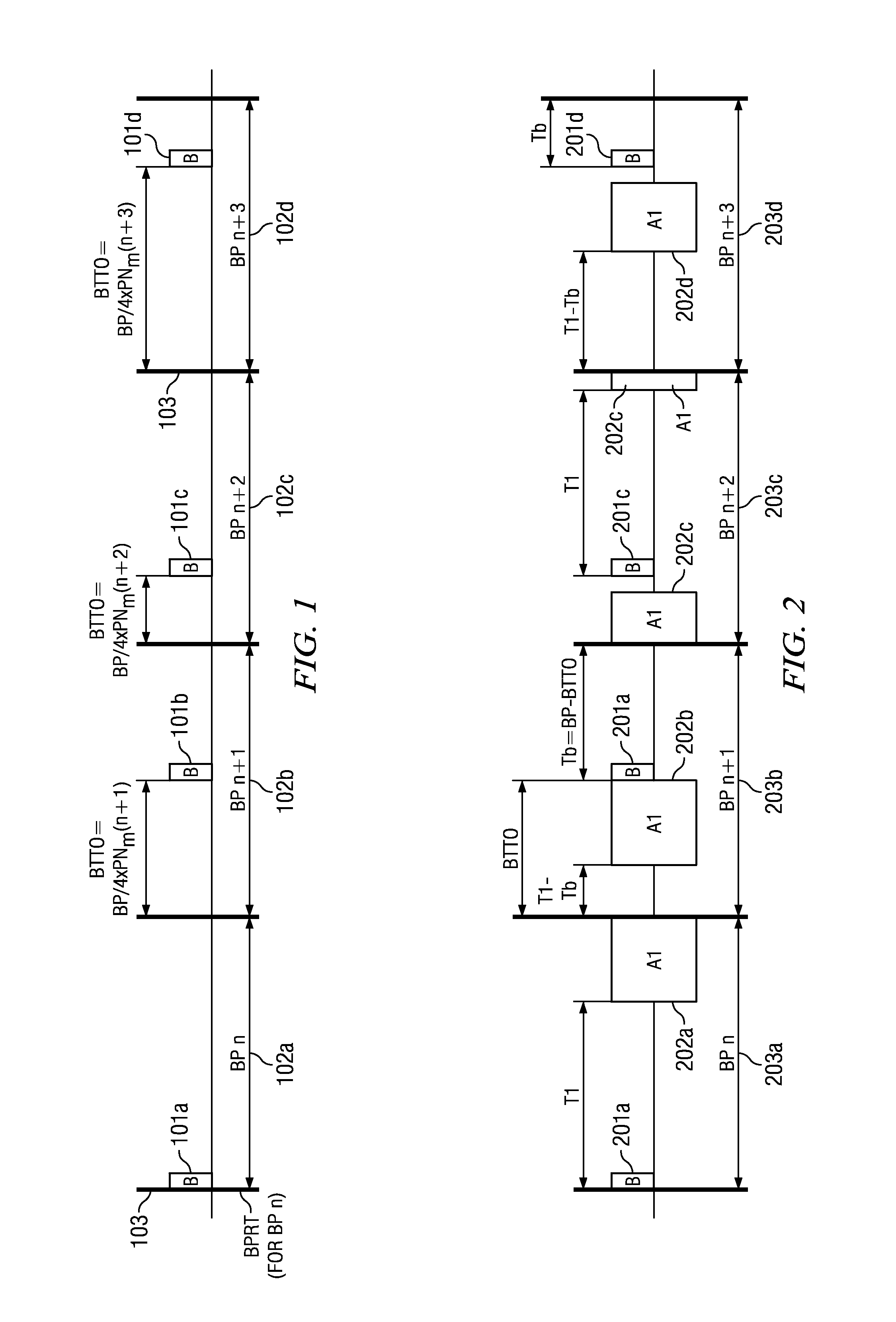
[0006]Groups of wireless devices or nodes are organized into networks, each having a network hub. Node access to a common channel is coordinated by the hub, but access is not coordinated between networks, which can result in inter-network interference. A beacon is transmitted by the hub in each beacon period. Each beacon contains timing, access, and capability information. The beacon transmission time, relative to the start of a beacon period, shifts from one beacon period to next according to a pseudo-random sequence. Different pseudo-random sequences are used by neighboring network hubs. Repeated collisions between inter-network beacons and other transmissions are circumvented when neighboring network hubs use different beacon shift sequences. The current shift sequence index and the phase of the shift sequence are encoded in the beacon frame, which allows each node in the network to readily determine the next beacon time.
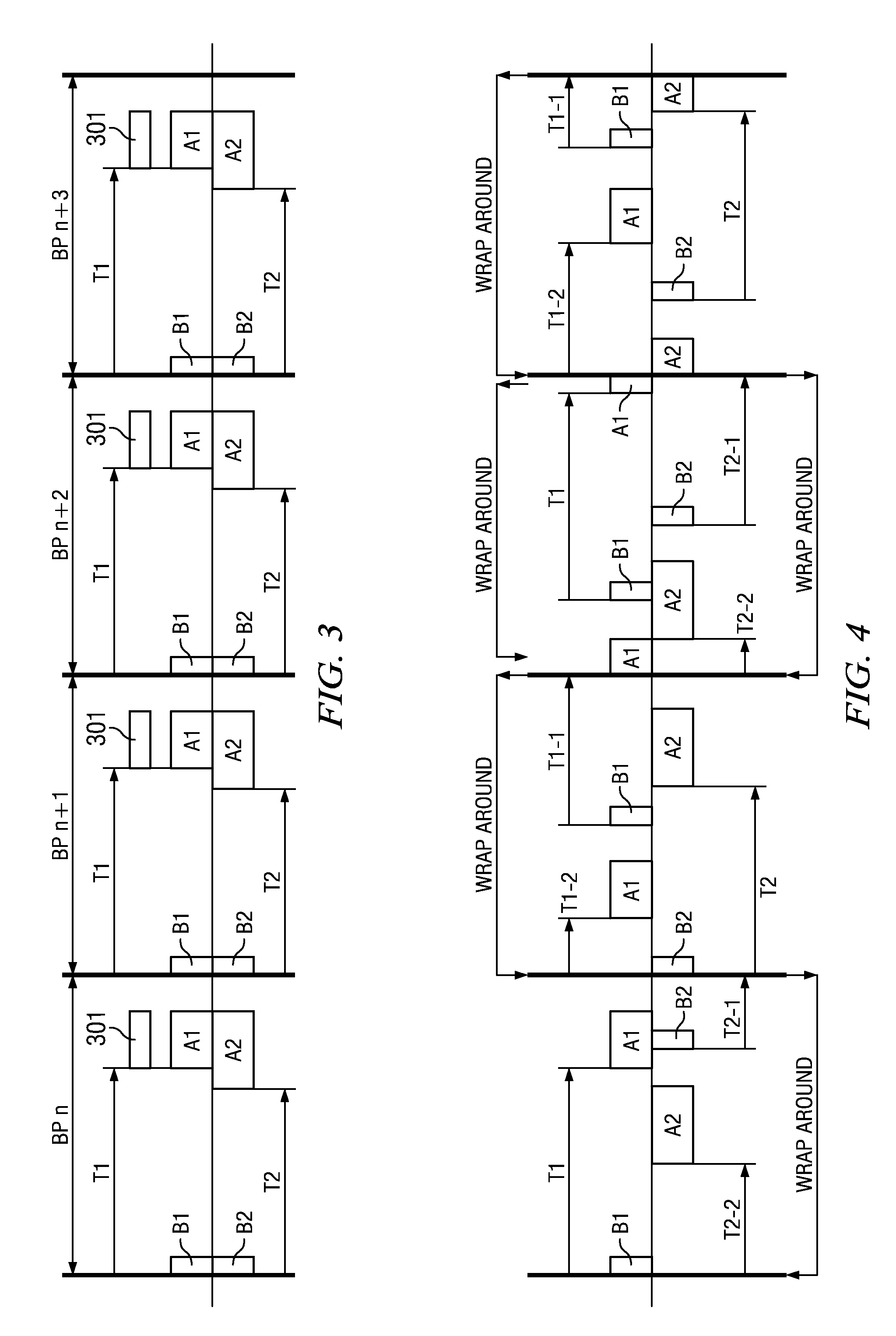
[0008]Embodiments of the invention minimize or prevent inter-network interference by rotating the beacon transmission times from one beacon period to next. As a result of shifting beacon transmission times, the allocated intervals for each node in the network are shifted from one beacon period to next as well. Beacon transmission times are encoded in a beacon frame by the transmitting hub, which allows nodes in the hub's network to identify their respective allocation intervals. Hubs may independently or jointly choose their own beacon shifting patters without exchanging time sharing messages between them.

Problems solved by technology

Node access to a common channel is coordinated by the hub, but access is not coordinated between networks, which can result in inter-network interference.

Method used


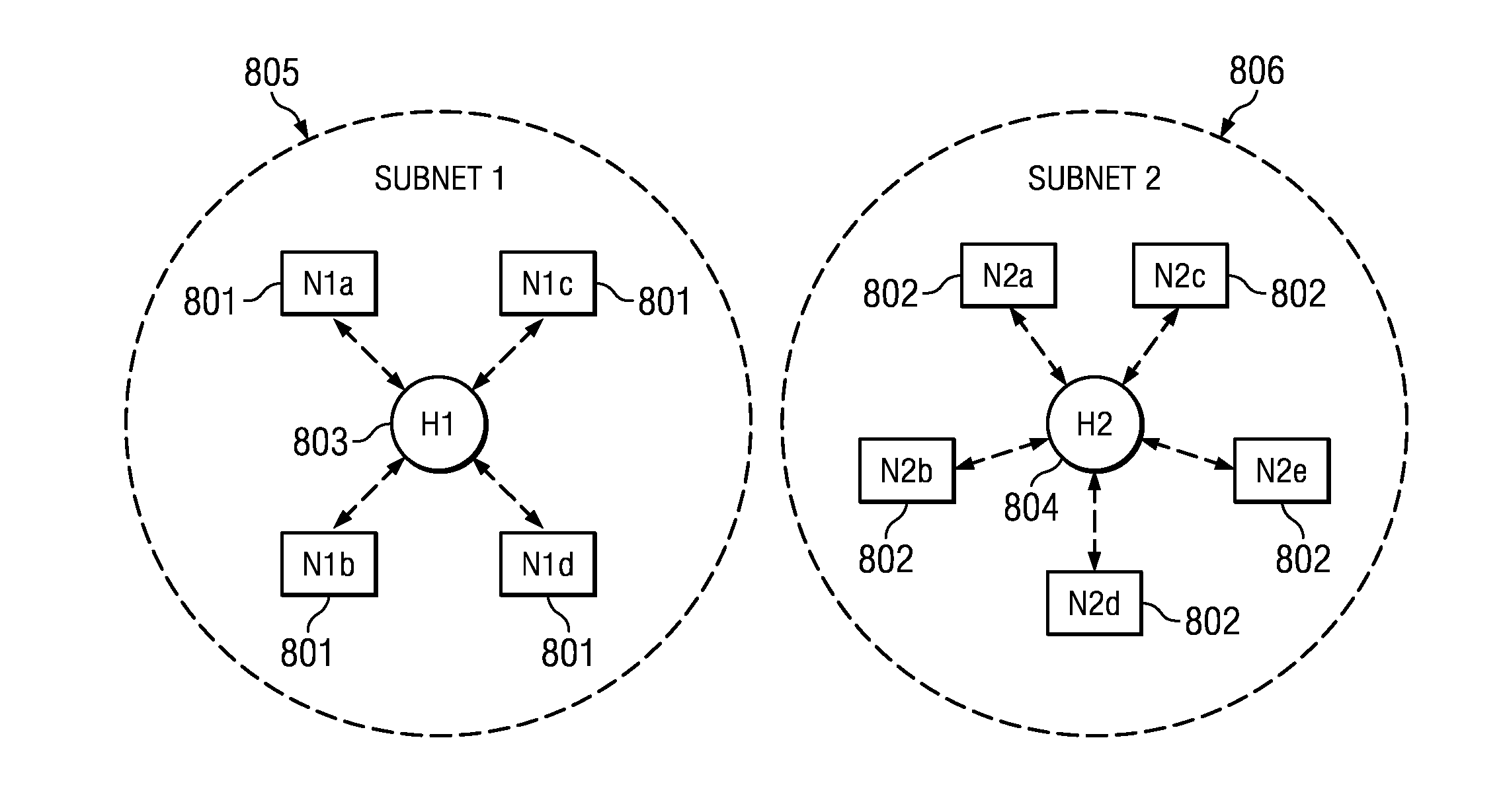
Image

  • Mitigation of Interference Between Wireless Networks
  • Mitigation of Interference Between Wireless Networks
  • Mitigation of Interference Between Wireless Networks

Examples


Embodiment Construction

[0019]The invention now will be described more fully hereinafter with reference to the accompanying drawings. This invention may, however, be embodied in many different forms and should not be construed as limited to the embodiments set forth herein. Rather, these embodiments are provided so that this disclosure will be thorough and complete, and will fully convey the scope of the invention to those skilled in the art. One skilled in the art may be able to use the various embodiments of the invention.

[0020]In one embodiment, a group of wireless devices form an ad hoc network with one of the devices acting as a network hub. Among other functions, the hub is responsible for coordinating the transmission time of each of the nodes in the network and for resolving transmission time conflicts to prevent or minimize intra-network interference.

[0021]The hub transmits a beacon frame B that is used as a reference point by the nodes within the hub's network to determine each respective node's ...


PUM


Abstract

A system and method for minimizing or preventing interference between wireless networks is disclosed. A network hub broadcasts a beacon signal within repeating beacon periods. The position of the beacon signal shifts within each beacon period based upon a predetermined pseudo-random sequence. The beacon signal includes data identifying the current beacon shift sequence and the current phase of the sequence. Neighboring hubs independently or jointly determine and broadcast their own beacon shift sequences and phases for their respective networks from a predetermined list. Nodes connected with the network hubs are assigned allocation intervals having a start time that is set relative to the beacon signal. The start time and duration of the allocation interval wraps around the beacon period if the allocation-interval would otherwise start or continue in a next beacon period.

Description

CROSS-REFERENCE TO RELATED APPLICATIONS[0001]The present application claims the benefit of the filing date of U.S. Provisional Patent Application No. 61 / 148,620, which is titled “Mitigation of Interference between Wireless Networks” and filed Jan. 30, 2009, the disclosure of which is hereby incorporated by reference herein in its entirety.TECHNICAL FIELD[0002]Embodiments of the invention are directed, in general, to coexistence between wireless networks and, more specifically, to mitigating inter-network interference by changing the transmission time of a beacon reference signal.BACKGROUND[0003]Mutual interference between wireless devices is a well-known problem. At a basic level, when two devices attempt to exchange information, the devices typically coordinate their transmit times so that they are not transmitting to each other simultaneously. When more devices are added to form a network, each additional device must also coordinate its transmit time so that two or more devices do...

Claims


Application Information

Patent Timeline
IPC IPC(8): H04B15/00H04W72/04
CPCH04B15/00H04W48/12
Inventor HO, JIN-MENG
Owner TEXAS INSTR INC
Learn More