Apparatus and method for improving the control of a concrete screeding machine

a technology of concrete screeding machine and control apparatus, which is applied in the direction of propulsion unit arrangement, roads, constructions, etc., can solve the problems of increasing the difficulty of maneuvering forklift machines along the aisles, and the flatness or levelness errors of concrete floors become a limiting factor in the practical design, and the cost is an important factor

Inactive Publication Date: 2010-08-05
SOMERO ENTERPRISES INC
View PDF62 Cites 48 Cited by
  • Summary
  • Abstract
  • Description
  • Claims
  • Application Information

AI Technical Summary

Benefits of technology

[0018]The present invention provides a screeding machine that comprises at least one of (a) a boom speed cruise control for automatically controlling the travel speed of the screed head assembly, (b) an auto-stabilizer control that automatically adjusts the stabilizer actuators of the screeding machine to a preselected degree of extension, (c) a control for automatically controlling the lowering of the screed head assembly toward and to the concrete surface and automatically activating the auger and vibrator at a beginning of each screeding pass and automatically deactivating the auger and vibrator in response to the screed head assembly being raised away from the concrete surface at the end of a screed pass, and (d) an auto-screed mode that allows the operator to select maximum values for at least one of a boom extension speed, a boom retraction speed, a boom rotation speed and a screed head rotation speed.
[0020]Optionally, the screeding head assembly may have an auger and a vibrating member for screeding the concrete surface, and may further comprise auger bearings for rotatably supporting the auger. The screeding head assembly may include an adjustment mechanism that allows an operator of the screeding machine to change the auger bearings and the auger without having to adjust a height adjustment of the auger after reassembly of the auger bearings and the auger, whereby the auger height adjustment settings are maintained without any readjustment. Optionally, the screeding head assembly may include a pair of detachable transport stands for supporting opposite ends of the screed head assembly at a support surface when the screeding machine is being transported.

Problems solved by technology

Large vertical offset errors at the forklift forks result in an increasingly greater difficulty in maneuvering the forklift machines along the aisles and while reaching for materials and goods at the upper most shelves.
Therefore, flatness or levelness errors in the concrete floor become a limiting factor in the practical design of high-density vertical-storage warehouse facilities.
In locations where land or real estate values are high or available space is at a premium, such costs are an important factor.
Super-flat floors are typically expensive for building owners to buy and concrete contractors to produce, since such projects usually require specialized equipment and experienced personnel with a thorough working knowledge of the process.
Because of the relatively higher cost of the super-flat floors, often only specified areas of a building floor will be made to super-flat specifications, such as within anticipated aisleways of a given floor plan.
When changes for the floor plan are necessary however, the spacing and location of the aisle ways cannot be easily adjusted or moved.
This limitation increases renovation costs and possibly reduces the future investment value and long-term usefulness of the facility.
Super-flat concrete floors are much more difficult and expensive to achieve than those conventionally poured.
However, a large number of workers are required to finish the floor.
Production speed of the floor is thus relatively slow with such a conventional process.
Additionally, as even the best skilled worker continues to use his tools of the trade, over the course of a day, the worker will fatigue and tire as the day goes on.
Human endurance has its typical limitations.
This factor can also have an adverse effect on the final F-numbers and quality of the floor.
Therefore, because many flat surfaces are finished by manual labor, the surfaces are likely to have relatively poor or inconsistent quality with regard to overall levelness and flatness.
There exist, however, limitations toward achieving large areas of highly accurate and flat screeded concrete of having a high degree of perfection and super-flat high quality floors that are a result of the above-described physical aspect.
However, access to the concrete surface can be a limitation.
Workers using these tools may be greatly limited during “wide placement” site conditions or high rates of production.
However, the actual accuracy of the finished concrete floor surface is likely to remain in question.
With high quality and super-flat concrete floors, however, the created landing depressions become an even greater limitation toward achieving high-quality floors having high F-number characteristics.
However, such soft landings can be difficult to achieve on a consistent or repeatable basis, and are largely dependent on the level of skill and experience of the screeding machine operator.
Similarly, the speed at which the operator retracts the boom and advances the screed head during screeding operations can affect the final quality and flatness of the concrete surface.
The length of time whereby this resiliency is lost is not easily determined and is subject to many variables such as the prevailing conditions that exist at the site or the mix design of the concrete.
Warm, dry and windy conditions may cause the concrete to quickly dry and harden at the surface, while cool and damp conditions may have the opposite effect.
Also, low slump concrete may be more difficult to work, but often offers higher cure strength by containing less water in the mixing ratio.

Method used


Image

  • Apparatus and method for improving the control of a concrete screeding machine
  • Apparatus and method for improving the control of a concrete screeding machine
  • Apparatus and method for improving the control of a concrete screeding machine

Examples


Embodiment Construction

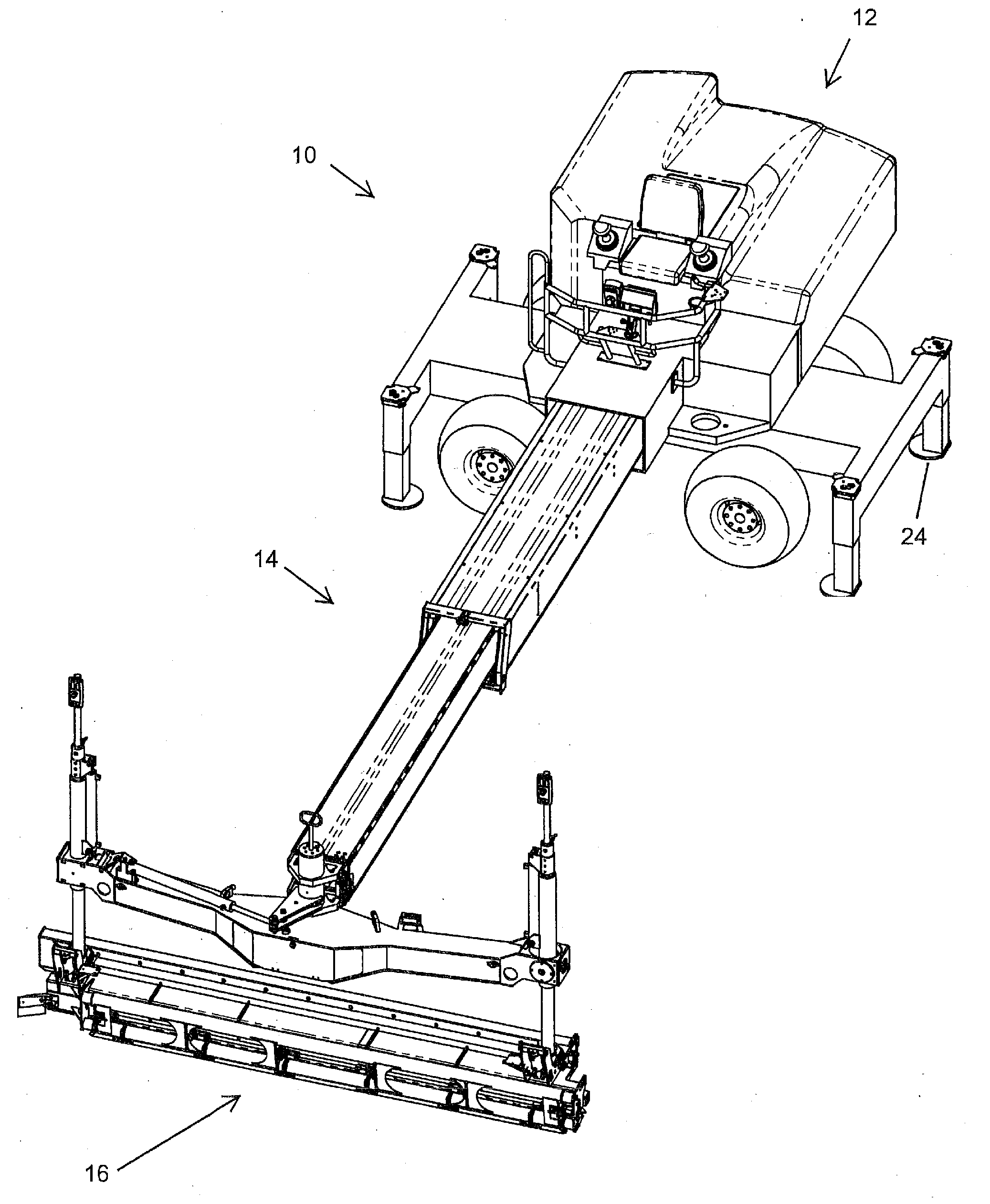
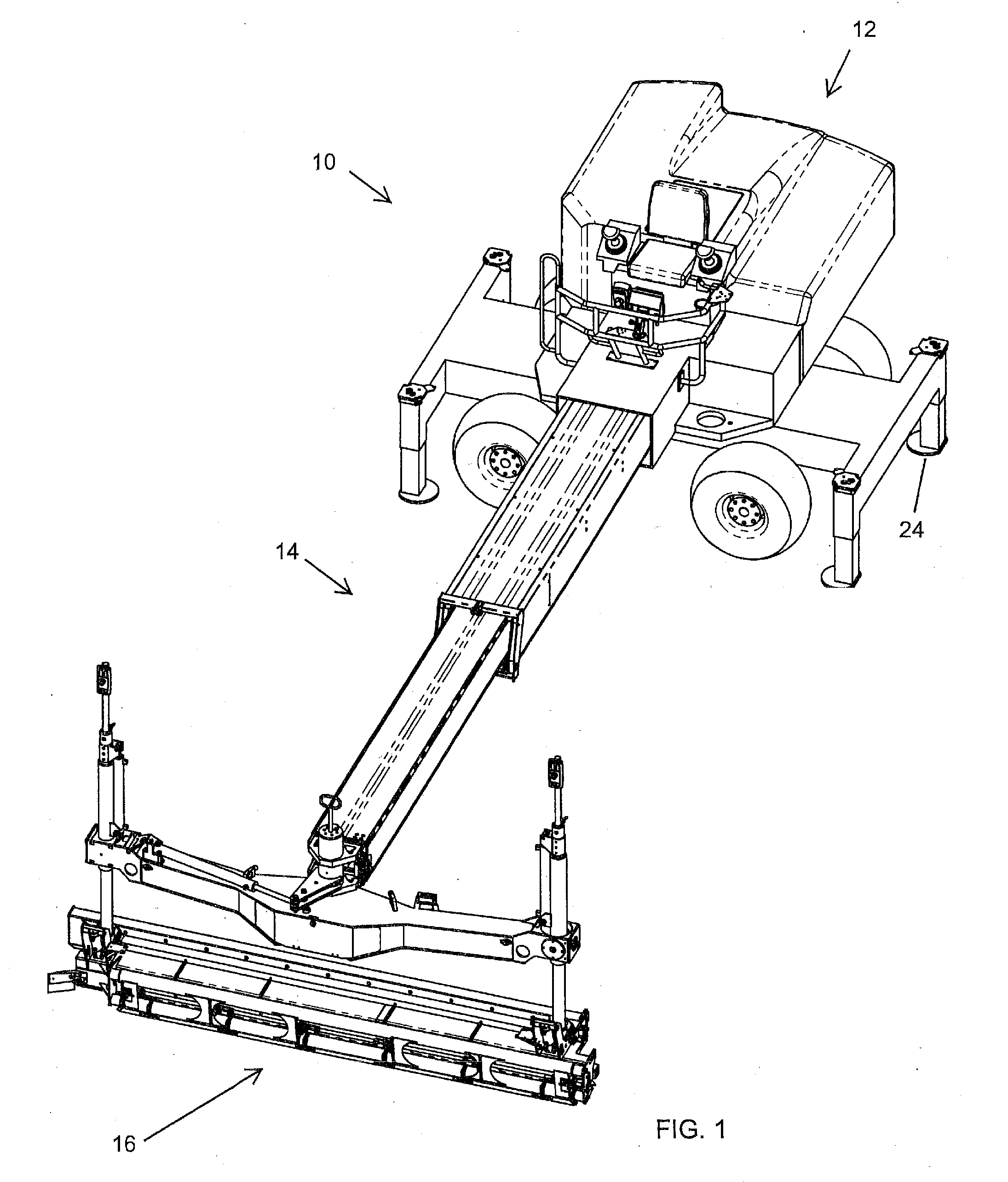
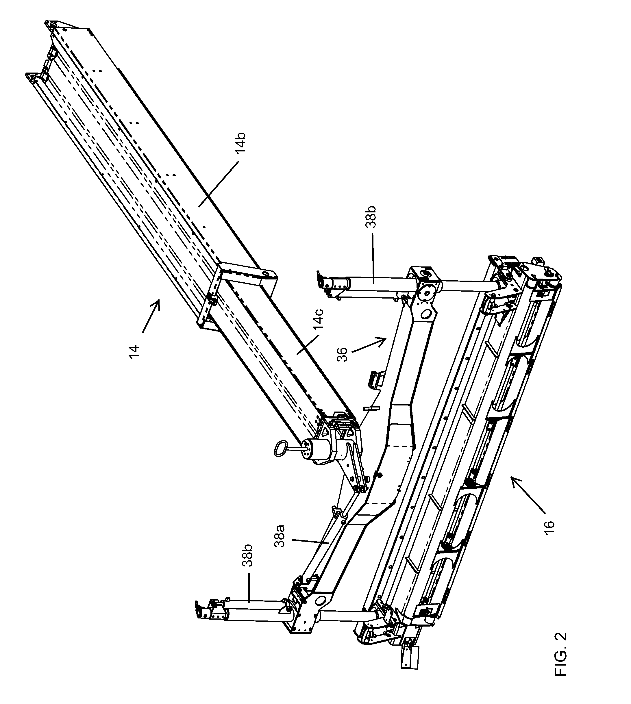
[0056]For the purposes of illustration and disclosure of the aspects of the present invention, a Somero SXP-D LASER SCREED™ screeding machine will be used as the example. However, clearly this example is not intended to limit the scope of the present application and clearly aspects of the present invention are suitable for use on other types of screeding machines.

[0057]A typical wide-placement concrete pour might consist of a set of eight to sixteen screeding passes from left to right before another row is started. This number of consecutive passes can typically complete the full-width of a typical wide-placement concrete pour. During each screeding pass made by a LASER SCREED™ screeding machine (or other suitable screeding machine or device) and its respective human operator, a number of human factor variables can come into play that can often affect the level of quality achieved in the final concrete surface. For instance, the travel speed of the screed head as it travels over the...


PUM


Abstract

A screeding machine including at least one of (a) a boom speed cruise control for automatically controlling the travel speed of the screed head assembly, (b) an auto-stabilizer control that automatically adjusts the stabilizer actuators of the screeding machine to a preselected degree of extension, (c) a control for automatically controlling the lowering of the screed head assembly toward and to the concrete surface and automatically activating the auger and vibrator at a beginning of each screeding pass and automatically deactivating the auger and vibrator in response to the screed head assembly being raised away from the concrete surface at the end of a screed pass, and (d) an auto-screed mode that allows the operator to select maximum values for at least one of a boom extension speed, a boom retraction speed, a boom rotation speed and a screed head rotation speed.

Description

CROSS REFERENCE TO RELATED APPLICATIONS[0001]The present application claims the benefit of U.S. provisional applications, Ser. No. 61 / 157,401, filed Mar. 4, 2009, and Ser. No. 61 / 149,092, filed Feb. 2, 2009, which are hereby incorporated herein by reference in their entireties.FIELD OF THE INVENTION[0002]The present invention relates generally to an apparatus and method for improving the control and productivity of a concrete screeding machine during the leveling and smoothing of freshly poured concrete that has been placed over a surface.BACKGROUND OF THE INVENTION[0003]There is a continuous and growing need within industry for flat and level close-tolerance concrete floors used in a variety of structures such as office buildings, shopping centers, warehouses, and production and / or manufacturing facilities. Most modern production and manufacturing plants include high-precision machinery and equipment which must be set level on a flat surface. A main benefit from achieving close-tol...

Claims


Application Information

Patent Timeline
Patent Type & Authority Applications(United States)
IPC IPC(8): E01C19/48
CPCE01C19/405B60K26/02
Inventor HALONEN, PHILIP D.KANGAS, MATTHEW A.KIERANEN, CARL B.ANDERSON, FRANK E.
Owner SOMERO ENTERPRISES INC
Why Eureka
Try Eureka