Leakage flow minimization system for a turbine engine

a technology of leakage flow and turbine engine, which is applied in the direction of machines/engines, liquid fuel engines, mechanical equipment, etc., can solve the problems of imbalance and recirculation of leakage flow, and achieve the effect of reducing the cross-sectional area of the interfa

Inactive Publication Date: 2010-08-05
SIEMENS ENERGY INC
View PDF33 Cites 24 Cited by
  • Summary
  • Abstract
  • Description
  • Claims
  • Application Information

AI Technical Summary

Benefits of technology

[0020]A portion of the seal housing can surround the flow guides. This portion of the seal housing can at least part

Problems solved by technology

The undulating seal can create imbalance

Method used


Image

  • Leakage flow minimization system for a turbine engine
  • Leakage flow minimization system for a turbine engine
  • Leakage flow minimization system for a turbine engine

Examples


Embodiment Construction

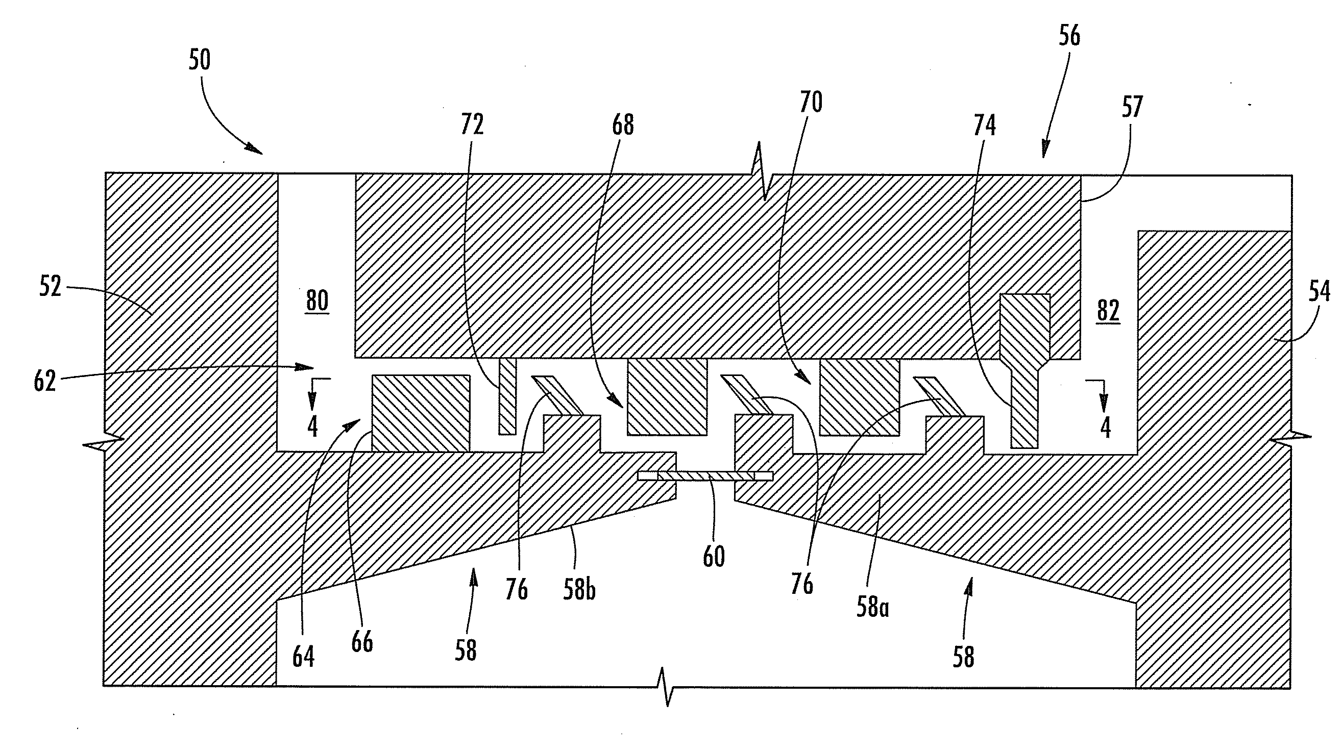
[0028]Aspects of the present invention relate to a system for reducing leakage flow in a turbine engine. Embodiments of the invention will be explained in connection with one potential leakage flow path between neighboring rotating and stationary turbine structures, but the detailed description is intended only as exemplary. Embodiments of the invention are shown in FIGS. 3-5, but aspects of the invention are not limited to the illustrated structure or application.

[0029]A sealing system according to aspects of the invention can be used in connection with an interface between neighboring rotating and stationary turbine components. FIG. 3 shows an example of one such interface 50 defined between at least an upstream rotor disk 52 and a stator 56. The term “stator” is intended to include any portion of a stationary vane, such as a ID shroud portion of the vane and / or a seal housing 57 or other structure attached to the vane. The interface 50 can further include a downstream rotor disk ...


PUM


Abstract

A sealing system is applied to the interface between a stator and a rotor in a turbine engine to minimize fluid leakage across the interface. One interface can be defined between portions of neighboring rotor disks and a stator. The sealing system includes one or more rows of flow guides, such as airfoils, provided on the rotor disk near the upstream end of the interface. These flow guides can impart tangential velocity on the leakage flow. One or more undulating seal structures can be connected to the stator downstream of the flow guides. These undulating seals can have a periodic waveform conformation. The undulating seals can create unsteadiness in the flow and recirculation of the leakage flow, which causes losses. The sealing system can also include other types of seals, such as labyrinth seals and brush seals, to further create a tortuous path for any leakage flow.

Description

FIELD OF THE INVENTION[0001]The invention relates in general to turbine engines and, more particularly, to a system for minimizing leakage flow in a turbine engine.BACKGROUND OF THE INVENTION[0002]FIG. 1 shows a cross-section through a portion of a turbine engine 10. The turbine engine 10 can generally include a compressor section 12, a combustor section 14 and a turbine section 16. A centrally disposed rotor 18 can extend through the three sections.[0003]The turbine section 16 can include alternating rows of stationary vanes 20 and rotating blades 22. Each row of blades can include a plurality of airfoils 22 attached to a disk 24 provided on the rotor 18. The rotor 18 can include a plurality of axially-spaced disks 24. The blades 22 can extend radially outward from the disks 24.[0004]Each row of vanes can be formed by attaching a plurality of airfoils 20 to the stationary support structure in the turbine section 16. For instance, the airfoils 20 can be hosted by a vane carrier 26 t...

Claims


Application Information

Patent Timeline
IPC IPC(8): F04D29/08
CPCF04D29/102F04D25/16
Inventor BEECK, ALEXANDER R.MHETRAS, SHANTANU P.
Owner SIEMENS ENERGY INC
Why Eureka
Try Eureka