Treated substrate having hydrophilic region and water repellent region, and process for producing it

a technology of hydrophilic region and treated substrate, which is applied in the direction of instruments, photomechanical devices, synthetic resin layered products, etc., can solve the problems of high cost of facilities, low utilization efficiency of energy, materials, etc., and complex photolithography processes. , to achieve the effect of simple apparatus, high contrast on the surface can, and high energy

Inactive Publication Date: 2010-08-05
ASAHI GLASS CO LTD
View PDF2 Cites 29 Cited by
  • Summary
  • Abstract
  • Description
  • Claims
  • Application Information

AI Technical Summary

Benefits of technology

[0015]By the present invention, a treated substrate having a hydrophilic region and a water repellent region, of which the contrast is high on its surface can be obtained. Further, without using a large facility, a vacuum apparatus and a high energy light source, the treated substrate can be produced. Namely, the treated substrate can be produced by using a simple apparatus and a simple light source with a low light amount in a short time.
[0016]Further, by using the treated substrate of the present invention, a member on which a pattern of a film made of a functional material is formed can be obtained, and the treated substrate of the present invention can be used for various applications.

Problems solved by technology

However, processes of the photolithography are complex, and utilization efficiency of energy, material, etc. is low.
Further, there is a problem such that since the processes of the photolithography are carried out in a clean room, cost of facilities is expensive.
However, in the ink-jet print method, position accuracy is low, and it is difficult to form a fine pattern.

Method used


Image

  • Treated substrate having hydrophilic region and water repellent region, and process for producing it
  • Treated substrate having hydrophilic region and water repellent region, and process for producing it
  • Treated substrate having hydrophilic region and water repellent region, and process for producing it

Examples


example 1

Substrate Wash

[0089]A 5 cm2 silicon wafer was washed with ethanol and then washed with UV / O3.

Preparation of a Coating Solution

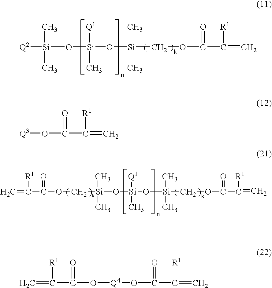
[0090]2.5 g of isopropanol was added in a sample vessel. 0.1 g of a 10 mass % isopropanol solution of a polydimethyl siloxane having methacryloyloxy propyl groups at both terminals (DMS-R18, manufactured by Gelest, Inc., the compound of the formula (21) wherein R1 is a methyl group, Q1 is a methyl group, k is 3, and the molecular weight is from 4,500 to 5,500) was added to the sample vessel. 0.2 g of a 1 mass % isopropanol solution of trimethylol propane triacrylate was added. 0.06 g of a 1% isopropanol solution of IRGACURE 369 (manufactured by CIBA-GEIGY Limited) was added as a photopolymerization initiator. The sample vessel was shaken a few times to mix the solution.

Coating with a Solution

[0091]The silicon wafer was coated with the prepared coating solution by spin coating under a condition of 3000 rpm for 20 seconds, and a film was formed.

Light Irradiatio...

example 2

[0096]The same operation was carried out as in Example 1, except that IRAGARACURE 907 (manufactured by CIBA-GEIGY Limited) was used, instead of IRAGARACURE 369. The thickness of the obtained film was 8 nm.

[0097]The contact angle to water of the obtained treated substrate was 21° at a non-irradiated part and 100° at an ultraviolet light irradiated part. Therefore, a water repellent-hydrophilic pattern having a hydrophilic region (contact angle: 21°) and a water repellent region (contact angle: 100°) was confirmed.

example 3

[0098]The same operation was carried out as in Example 2, except that 0.5 g of a 1% aqueous solution of a polyvinyl alcohol (molecular weight: 500, manufactured by KANTO CHEMICAL CO., INC.) was added to a coating solution, and after spin coating, the substrate was left to stand still for 5 minutes. The thickness of the obtained film is estimated to be about 12 nm.

[0099]The contact angle to water of the obtained treated substrate was 29° at a non-irradiated part and 100° at an ultraviolet light irradiated part. Therefore, a water repellent-hydrophilic pattern having a hydrophilic region (contact angle: 29°) and a water repellent region (contact angle: 100°) was confirmed.


PUM

PropertyMeasurementUnit
thicknessaaaaaaaaaa
contact angleaaaaaaaaaa

Abstract

To provide a treated substrate having a hydrophilic region and a water repellent region, of which contrast is high on its surface. Further, to provide a process for producing a treated substrate, wherein a specific equipment, light having a high energy or light irradiation for a long time is not required, and the treated substrate can be produced with a low amount of light for a short time.A treated substrate having a hydrophilic region and a water repellent region on a surface of a substrate, characterized in that the water repellent region is made of a water repellent film formed by curing the composition (A) comprising a photopolymerization initiator and a compound (a) having at least one (meth)acryloyl group, and a water repellent moiety and having a film thickness of from 0.1 to 100 nm. A process for producing a treated substrate, characterized by using a hydrophilic substrate or carrying out a hydrophilic treatment on a surface of a substrate to make the surface hydrophilic, then forming a film containing the composition (A) on the surface, then forming a water repellent film having a film thickness of from 0.1 to 100 nm by irradiating light on a part of the film surface to cure the composition (A) and then removing an uncured composition (A) present on the surface of the substrate in order to expose the hydrophilic surface.

Description

TECHNICAL FIELD[0001]The present invention relates to a treated substrate having a hydrophilic region and a water repellent region on a surface of a substrate, a process for producing it and a process for producing a member on which a pattern of a film made of a functional material is formed by using the treated substrate.BACKGROUND ART[0002]Many functional thin films are practically used in the fields of semiconductor devices, displays and luminescent elements. Functional thin films are formed by disposing a material having a desired property at a desired position, followed by patterning. The functional thin films are used as wiring, electrodes, insulating layers, luminescence layers, optical thin films, etc.[0003]For example, a photoresist pattern obtained by photolithography may be mentioned. However, processes of the photolithography are complex, and utilization efficiency of energy, material, etc. is low. Further, there is a problem such that since the processes of the photolit...

Claims


Application Information

Patent Timeline
Patent Type & Authority Applications(United States)
IPC IPC(8): B32B33/00B32B27/00C08F2/48B05D5/00
CPCG03F7/027G03F7/0755Y10T428/265H01L21/312G03F7/0757H01L21/02118Y10T428/3154Y10T428/31663Y10T428/31667G03F7/028
Inventor FURUKAWA, YUTAKA
Owner ASAHI GLASS CO LTD
Why Eureka
Try Eureka