Flexible magnetic interconnects

a magnetic interconnect and flexible technology, applied in the field of electric connectors, can solve the problems of limiting the shape and size of interconnected modules, affecting the design and manufacturing of different composite assemblies, and affecting the design of the connection, so as to achieve the effect of reducing the number of connectors

Active Publication Date: 2010-08-05
APEX TECH INC
View PDF85 Cites 148 Cited by
  • Summary
  • Abstract
  • Description
  • Claims
  • Application Information

AI Technical Summary

Benefits of technology

[0013]In further embodiments of the methods and systems disclosed herein, modules may comprise compliant contacts and magnetic structures that are free to rotate or translate in one or more dimensions. Such movement may be useful in compensating for mechanical differences or motion between multiple interconnected modules that prevent continuous mechanical contact between modules. In embodiments of the methods and systems disclosed herein, modules may be comprised of magnetic structures and compliant contacts that allow modules to rotate or translate relative to each other without breaking electrical continuity between modules.
[0019]In embodiments of the methods and systems disclosed herein, there is no requirement for rigid printed circuit boards, rigid or resilient electrical contact structures, stiff electrical contact support structures or housings. In addition, the design of flexible printed circuit boards and other compliant contact structures may be readily customized somewhat independently from the design of the larger mechanical structure of the modules. This ability to accommodate changes allows for flexibility in design and tooling flexibility. Since electrical contact mating pairs can be designed to function substantially independently, efficiencies in designing, fabricating and testing different composite assemblies from a small number of component designs may be gained. Cost efficiencies may be gained in the nesting or “panelization” of the flexible printed circuits, fabrication of mechanical structures for modules and standardization of a limited number of parts.
[0020]In one exemplary application, methods and systems for creating electrical interconnection between discrete lighting devices or modules are provided for fabricating assemblies of planar and three-dimensional structures utilizing magnetic force. Individual modules may be of virtually any flat or compound three-dimensional shape. The modules utilize magnetic structures and compliant electrical contact pads to provide electrical contact force. The magnetic forces can also be used to mechanically retain the modules in the desired shape. The interconnection method and system allows modules to be assembled, disassembled and reconfigured into extended structures without requiring tight mechanical tolerances on individual modules. Embodiments of the disclosed method and system may be applied in decorative and architectural lighting and signage. They may also be applied in other areas of electronic packaging and system assembly.

Problems solved by technology

These connection approaches have many limitations including, cost, awkward assembly techniques, bulky appearance, large size, restrictions on the shape and size of interconnected modules, fragility, alignment tolerances, difficulty in removing individual elements of extended assemblies and damage susceptibility.
For example, conventional pin and socket type interconnection methods are restricted in the shapes possible and in the direction of approach in mating assemblies.

Method used


Image

  • Flexible magnetic interconnects
  • Flexible magnetic interconnects
  • Flexible magnetic interconnects

Examples


Embodiment Construction

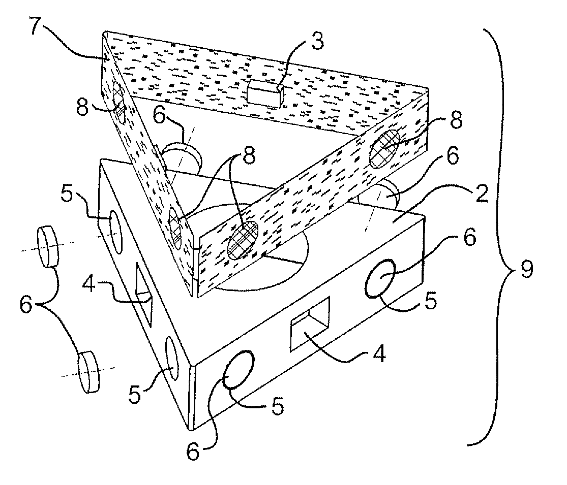
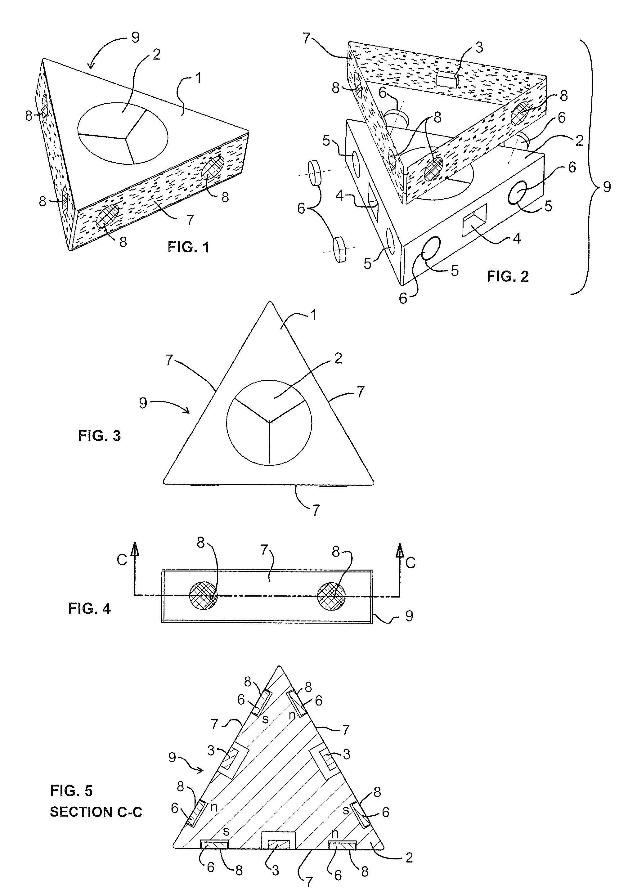
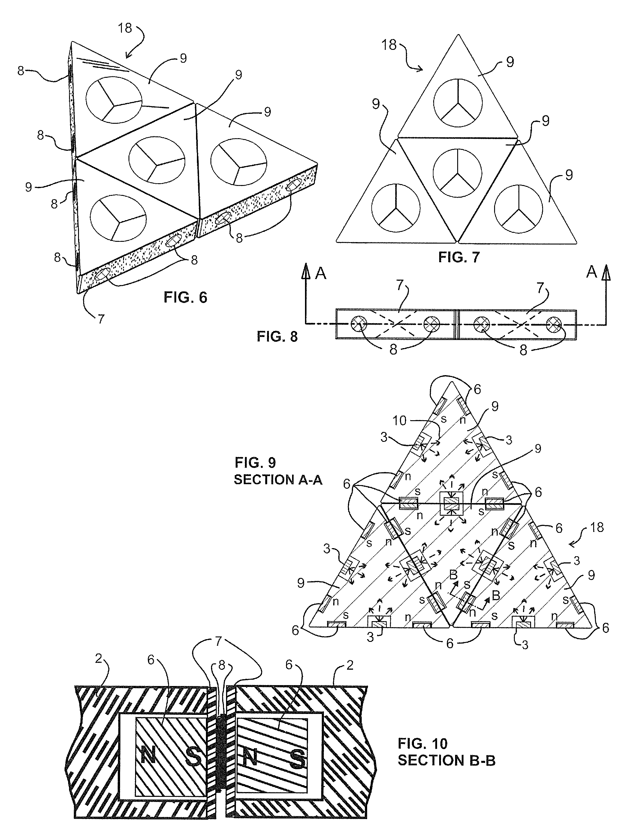
[0107]In some embodiments, the modular electrical interconnection methods and systems provided in this disclosure utilize permanent magnets in combination with flexible or compliant electrical circuit substrates or localized flexible contacts on a rigid substrate. The flexible / compliant electrical contact structures, when mated, are located substantially between permanent magnets of opposing modules, or between magnets on one module and ferromagnetic material on an opposing module. The attraction of opposing magnets of adjacent modules (or magnets and ferromagnetic areas), compresses the contact pads of the flexible circuitry, thus generating contact force for electrical interconnection, and also provides some attractive force to mechanically retain the modules together. Systems made from these modules can be easily and reversibly assembled. No elastic properties of the contact system are required for reliable functioning of this connector system. The electrical contacts are constan...


PUM

PropertyMeasurementUnit
thickaaaaaaaaaa
thickaaaaaaaaaa
diameteraaaaaaaaaa

Abstract

A flexible magnetic interconnect is disclosed. In one embodiment, an apparatus includes a module having a recess therein. A magnetic structure is moveable within the recess and a flexible circuit cooperates with the module to retain the magnetic structure within the recess. Movement of the magnetic structure is caused by magnetic attraction between the magnetic structure and an external magnetic structure. The flexible circuit includes a compliant contact, which changes shape by movement of the magnetic structure.

Description

CROSS-REFERENCE TO RELATED APPLICATIONS[0001]This application claims the benefit of U.S. Provisional Application No. 61 / 206,609 filed Feb. 2, 2009, which is hereby incorporated by reference. This application also claims the benefit of U.S. Provisional Application No. 61 / 279,391 filed Oct. 20, 2009, which is hereby incorporated by reference.FIELD OF THE INVENTION[0002]The present invention relates generally to electrical connectors and, more particularly, to flexible magnetic interconnects.BACKGROUND OF THE INVENTION[0003]Electrical interconnections, such as between individual electronic and lighting modules to form a larger system, have typically been accomplished through the use of conventional connector systems such as pins, sockets, pressure connections, and other commercially available connector styles used to make board-to-board, board-to-cable, module-to-board and cable-to-cable or other separable connections. More permanent electrical interconnections may be formed with solde...

Claims


Application Information

Patent Timeline
Patent Type & Authority Applications(United States)
IPC IPC(8): H01R11/30H01F1/00
CPCA63F2009/1033H01R11/30H01R12/79H01R12/91H01R13/2407F21Y2101/02Y10S439/928F21S2/005F21V21/005F21V21/096H01R13/6205F21Y2115/10
Inventor RUDISILL, CHARLES ALBERTWHITTLE, DANIEL JOHN
Owner APEX TECH INC
Why Eureka
Try Eureka