Method and apparatus for manufacturing a liquid crystal component

a technology of liquid crystal components and manufacturing methods, which is applied in the manufacture of electrode systems, instruments, electric discharge tubes/lamps, etc., can solve the problems that the display of liquid crystal panels is sometimes difficult to see under the light of the sun

Inactive Publication Date: 2010-08-05
TORAY ENG CO LTD
View PDF0 Cites 31 Cited by
  • Summary
  • Abstract
  • Description
  • Claims
  • Application Information

AI Technical Summary

Benefits of technology

[0039]According to the method and the apparatus for manufacturing a liquid crystal component according to the present invention, as for the technology concerning the optical resin which has been recently developed and disclosed, the optical resin layer can be formed in a surely desirable shape between the panel surface of the liquid crystal module and the transparent cover with no unnecessary protrusion. That makes it possible to correspond with a mass production utilizing this optical resin.
[0040]FIG. 1 is a block diagram showing an example of the manufac

Problems solved by technology

For example, the display from the liquid crystal panel som

Method used


Image

  • Method and apparatus for manufacturing a liquid crystal component
  • Method and apparatus for manufacturing a liquid crystal component
  • Method and apparatus for manufacturing a liquid crystal component

Examples


Embodiment Construction

[0080]Hereinafter, desirable embodiments of the present invention will be explained referring to figures.

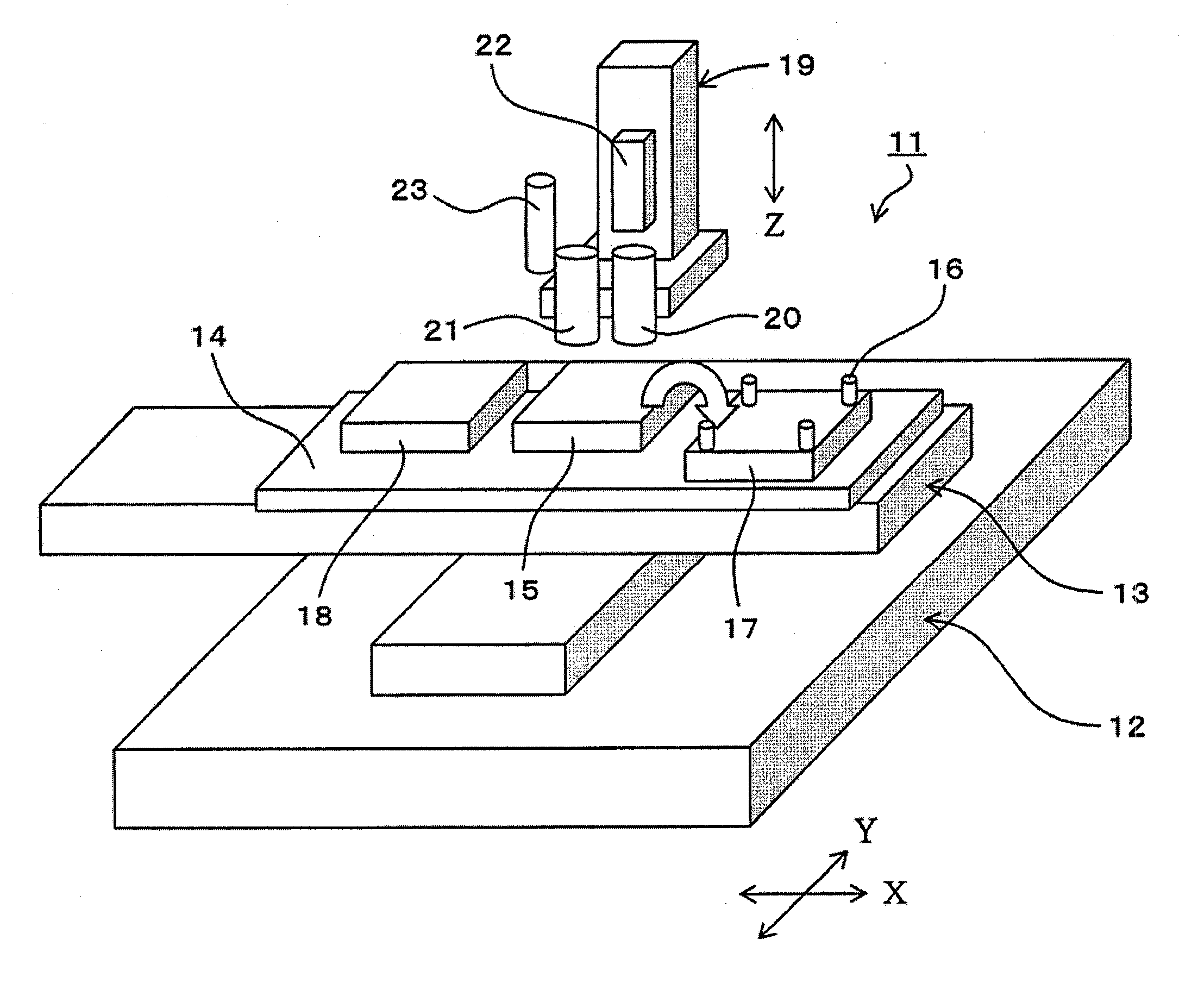
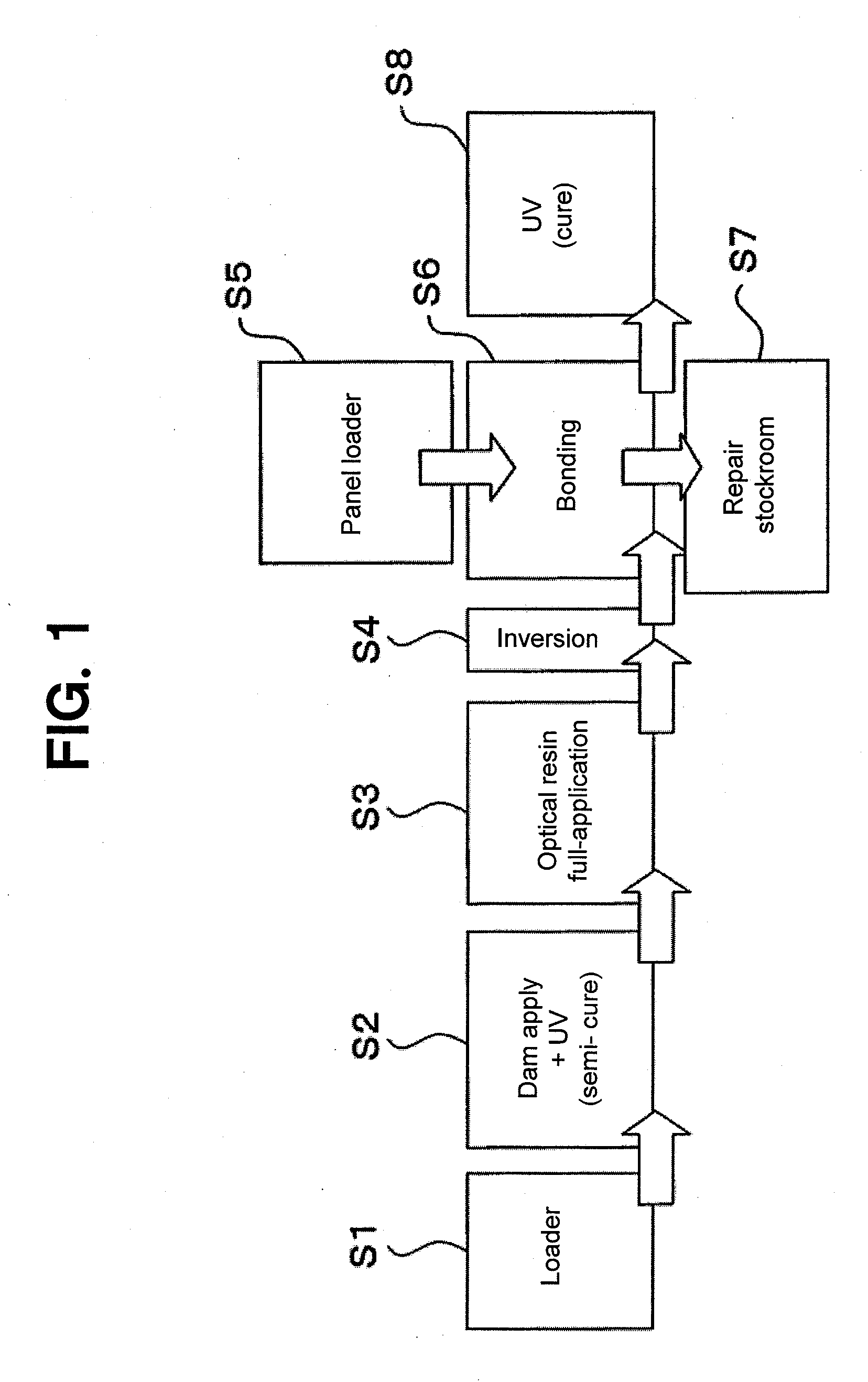
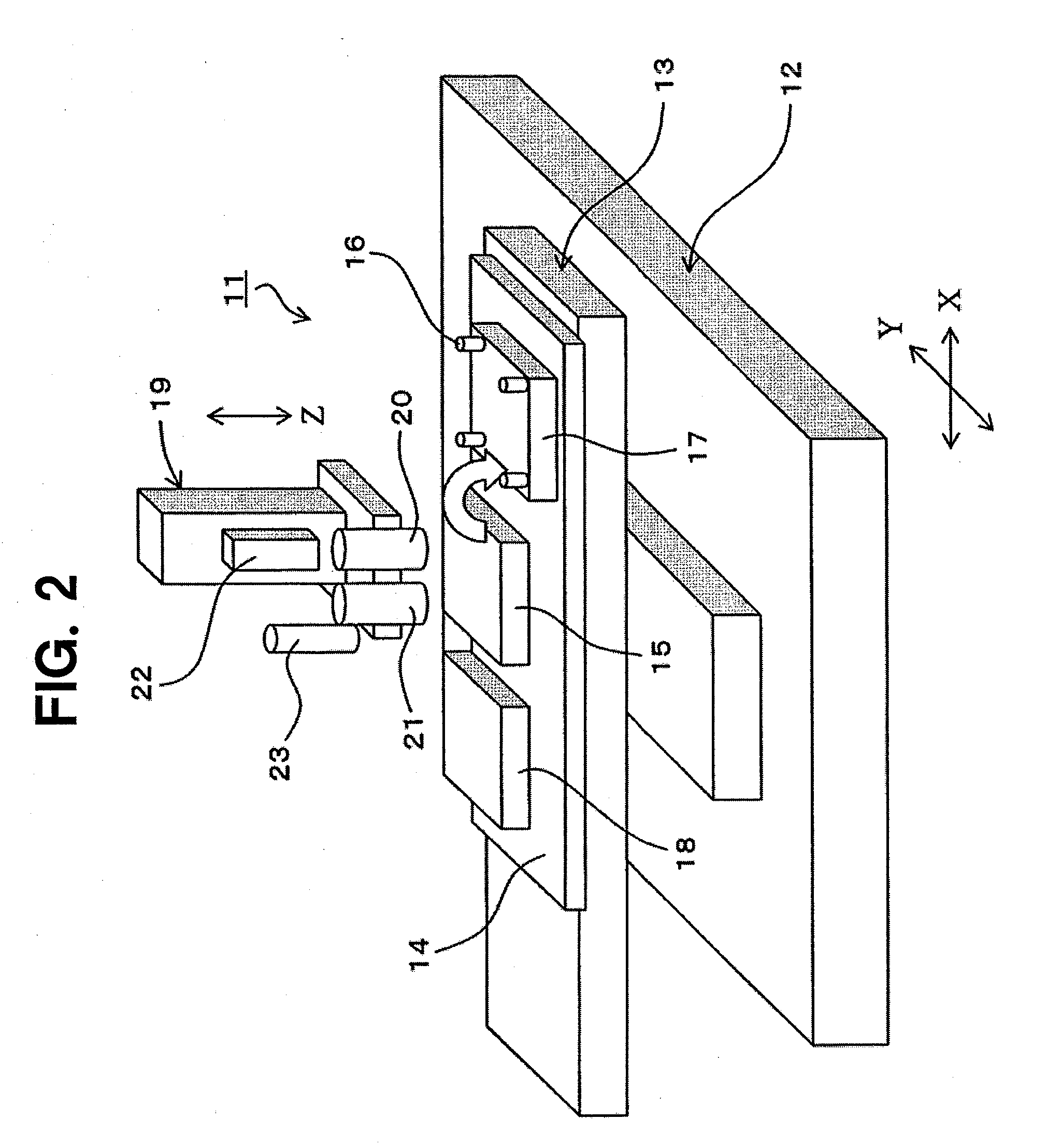
[0081]FIG. 1 shows an example of each step for a manufacturing method of a liquid crystal component according to an embodiment of the present invention, and FIG. 2 shows a schematic structure of a manufacturing method of a liquid crystal component according to an embodiment of the present invention. At first in the example shown in FIG. 1, in step S1 a transparent cover to be bonded with a liquid crystal module is carried by a loader, for example, and in step S2 an optical resin (ultraviolet cure resin) to form a transparent dam is applied on the peripheral part of the top surface of the transparent cover, and at the same time, ultraviolet ray (UV) is irradiated to the applied resin so that the resin is semi-cured to form a dam in a predetermined shape. In step S3, the optical resin is applied to the central section of the top surface of the transparent cover (main application), ...


PUM


Abstract

Provided is a liquid crystal component manufacturing method wherein a gap between a panel surface of a liquid crystal module and a transparent cover is filled with a transparent resin, then, the liquid crystal module and the transparent cover are bonded by curing the resin. In the method, at the peripheral section of at least one surface of the panel surface and the facing surface of the transparent cover, the resin is applied, then, a dam is formed by semi-curing the resin. At the same time, the resin is applied to the center, the panel surface and the transparent cover are permitted to face, and the resin applied at the center is pushed to spread by reducing the gap between the facing panel surface and the transparent cover. The resin pushed to spread is dammed up by the dam, and the whole resin that exists in the gap is cured. An apparatus for manufacturing the liquid crystal component is also provided. An optical resin layer recently developed and made known to the public is formed between the liquid crystal module panel surface and the transparent cover in desirable mode.

Description

TECHNICAL FIELD OF THE INVENTION [0001]The present invention relates to a method and an apparatus for manufacturing a liquid crystal component, and specifically relates to a method and an apparatus for manufacturing a liquid crystal component, in which when a gap between a panel surface of a liquid crystal module and a transparent cover is filled with a predetermined resin to bond both of them, the bonding can be performed to make a good condition which is targeted.BACKGROUND ART OF THE INVENTION [0002]A display of a liquid crystal module used in cellular phones or various display devices conventionally has an air gap structure in which a gap (air gap) in a range of about 0.5-1 mm is provided between a panel surface of the liquid crystal module and a transparent cover such as a tempered glass plate or an acrylic plate, so as not to influence the liquid crystal module even in a case that the cover is broken by an external impact.[0003]However, in this air gap structure, because a liq...

Claims


Application Information

Patent Timeline
IPC IPC(8): H01J9/26H01J9/46
CPCG02F1/1303G02F2202/28G02F2201/38G02F1/1333
Inventor NARABA, SATORUHIRATA, HAJIMETAHARA, TAKANORIARAI, YOSHIYUKINOGAMI, YOSHIO
Owner TORAY ENG CO LTD
Why Eureka
Try Eureka