Biological navigation device

a technology for biological navigation and luminal cavities, applied in medical science, surgery, diagnostics, etc., can solve the problems of high part count, high cost of a lower cost, patient danger, etc., and achieve the effect of reducing creasing and high packing density

Inactive Publication Date: 2010-08-05
LOMA VISTA MEDICAL
View PDF16 Cites 19 Cited by
  • Summary
  • Abstract
  • Description
  • Claims
  • Application Information

AI Technical Summary

Benefits of technology

[0033]The device can have one or more pressurizable tubes. The tubes can be ‘scrunched’ or folded at the front. The tube material can all be located distal or proximal to an ariticulatable steering section on the elongated element. The tube material can be partially located distal to the tip steering section. The tube material can be entirely located proximal to the tip steering section. The tubes can be sequentially staggered. After each lengthwise portion, the tube can have a sudden step-wise reduction in diameter, including equivalent to the previous section's diameter minus the walls thicknesses. This could create a steadily sequentially smaller diameter tube that packs well. The tubes can have tapered segments coupled with other elements, including staggers or straight sections. The tube can be configured to minimize creasing and have high packing densities during tube storage.
[0035]High pressure fluid can be delivered to the base. The fluid can be water or saline. The fluid can be delivered via a pump. The fluid can be delivered by a piston that is moved by an actuator; this method serves to minimize stored system energy. As the piston is driven, it can increase pressure which, when released to the tube can lead to the extension of the pressure tube. When the piston is withdrawn, it can create a vacuum that serves to evacuate a significant portion of the fluid in the tube.
[0036]The development of disposable cartridges can reduce or eliminate cleaning costs, cleaning trouble, and the risk inherent to reused devices. The risk of a poorly cleaned elongated element can be reduced because the elongated element can be substantially covered by the pressurizable tube.
[0037]The disclosed system, device or elements thereof can be used as elements that are combined into dedicated systems, as portions of dedicated systems (portions that can be reusable and portions that can be separable on a case-by-case basis, with some reused and some disposed of, sometimes referred to as ‘semisposables’ or ‘resposables’), or as additive elements to existing systems (i.e., retrofit device). Disposable systems only need to function for limited life, and they do not have to interface with other components again and again. Semisposable varieties can utilize a very high-quality, higher-cost core device portion, and lower cost, single-use portions. The single use portions can negate the need for most of the typical cleaning, for example for the sheath exposed portions. Adding to existing systems can leverage large installed bases, methods, and usage patterns.

Problems solved by technology

However, as disposable and other lower-cost colonoscopes are developed, these articulatable sections are no longer practical.
Their high part count creates total costs that are exorbitant for a lower cost, disposable device.
The pivot pins can also fall out, which can create a patient danger.
Their design geometries, while suited for long life, high cost, high strength metals elements, don't readily suit themselves to the design goals of lower-cost and more readily mass-produced parts.
Navigating the long, small diameter colonoscope shaft in compression through the colon—a circuitous route with highly irregular anatomy—can be very difficult.
Even with the achievement of such a practice milestone, the cecum is often not reached, thereby denying the patient the potential for a full diagnosis.
During colonoscopy, significant patient pain can result.
The primary cause of pain is thought to be stretching and gross distortion of the mesocolon (the mesentery that attaches the colon to other internal organs).
While attempting to advance the tip by pushing on the scope, often all that occurs is that intermediate locations are significantly stretched and grossly distorted.
Anesthesia delivery results in the direct cost of the anesthesia, the cost to professionally administer, the costs associated with the capital equipment and its facility layouts, and the costs associated with longer procedure time (e.g., prep, anesthesia administration, post-procedure monitoring, and the need to have someone else drive the patient home).
Cleaning of colonoscopes is also an issue.
Cleaning is time consuming, and lack of cleaning can result in disease transmission.
Cleaning also creates significant wear-and-tear of the device, which can lead to the need for more servicing.
However, multiple challenges exist for evening systems.
One typical challenge is the differential speed between the center lumen and the tip.
This can make it difficult to try to solve the 2:1 problem in a typical everting tube by sliding elements in the inner diameter or central region.
This 2:1 advancement issue and the pressure clamping can make it difficult to locate traditional colonoscope tip elements at the everting tip's leading edge.
Given that the tube is often long and pressurized, it therefore often precludes the ability to create a functioning center working channel.
Another issue is internal drag.
Material (e.g., tube wall) fed to the tip can cause increased capstan drag, for example the overall system advance force can be retarded to the point of stopping extension.
Optimal material selection is a highly significant challenge.
Monolithic materials have proven insufficient at providing the variety of requisite specifications.
It can be difficult to create a system that is of adequately low stiffness.
Larger diameters create higher propulsive forces, but they also do not typically readily conform to the colon in a lumen-centric manner and can be overly stiff.
This is time consuming and creates an undesirably non-continuous and geometrically interrupted procedure.
It is also very difficult to create ‘correct’ undesirable relative motion to a deflated structure that essentially is no longer a structure.
However, it has yet to be commercialized, it is very complicated, creates an undesirably larger diameter instrument, has lubrication leakage issues, and breaks down at longer advance lengths.
Additionally, colonoscopic devices have found it notably challenging to create methods to steer through torturous geometries, particularly without undue colon wall stresses and subsequent mesocolon stretch.
Steering kinematics have been an ongoing challenge—certainly for existing colonoscopes (which result in ‘looping’), but also to more effective next-generation devices.
When a propulsion tube section's leading edge then has a steering section more distal, with typically a camera, lighting source, and working channel exit at the tip, the steering is less than effective when going around a corner: A situation is created in which the tip is retroflexed and is pointing in one desired direction of advance, but the system's advance is in an exactly opposite direction.
In a colonoscopy, this wall interaction is undesirable—it creates unnecessary wall stress and trauma, and can be a significant contributor to gross wall distortion, known as looping.
This effect compromises subsequent kinematics and the desired tip-based propulsion, which can lead to undesirable affects such as looping.

Method used


Image

  • Biological navigation device
  • Biological navigation device
  • Biological navigation device

Examples


Embodiment Construction

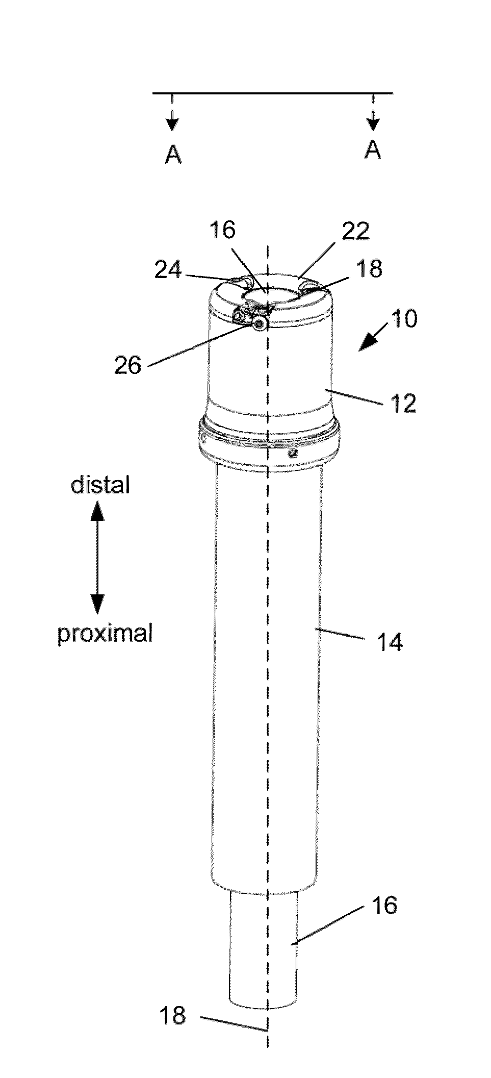
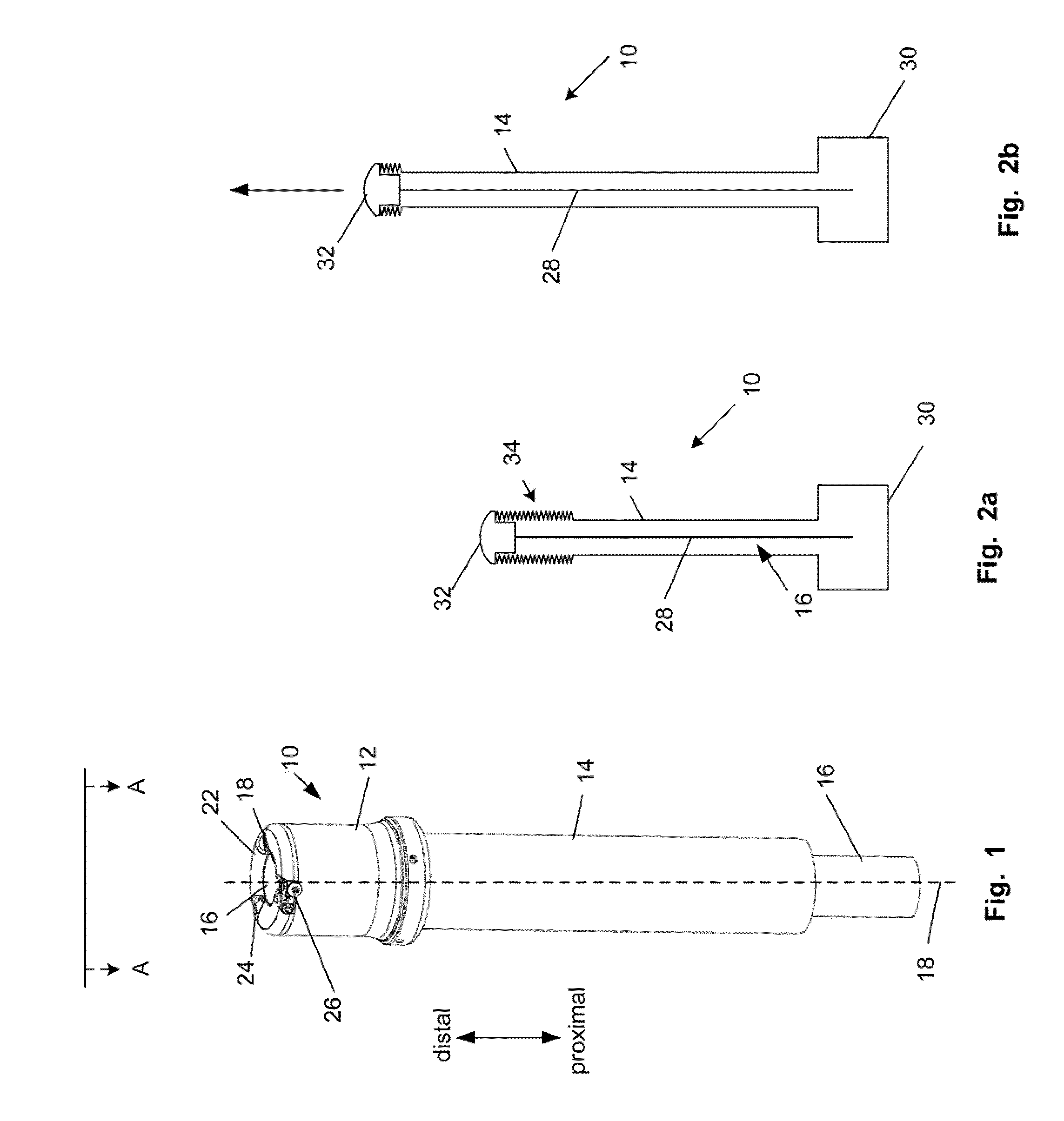
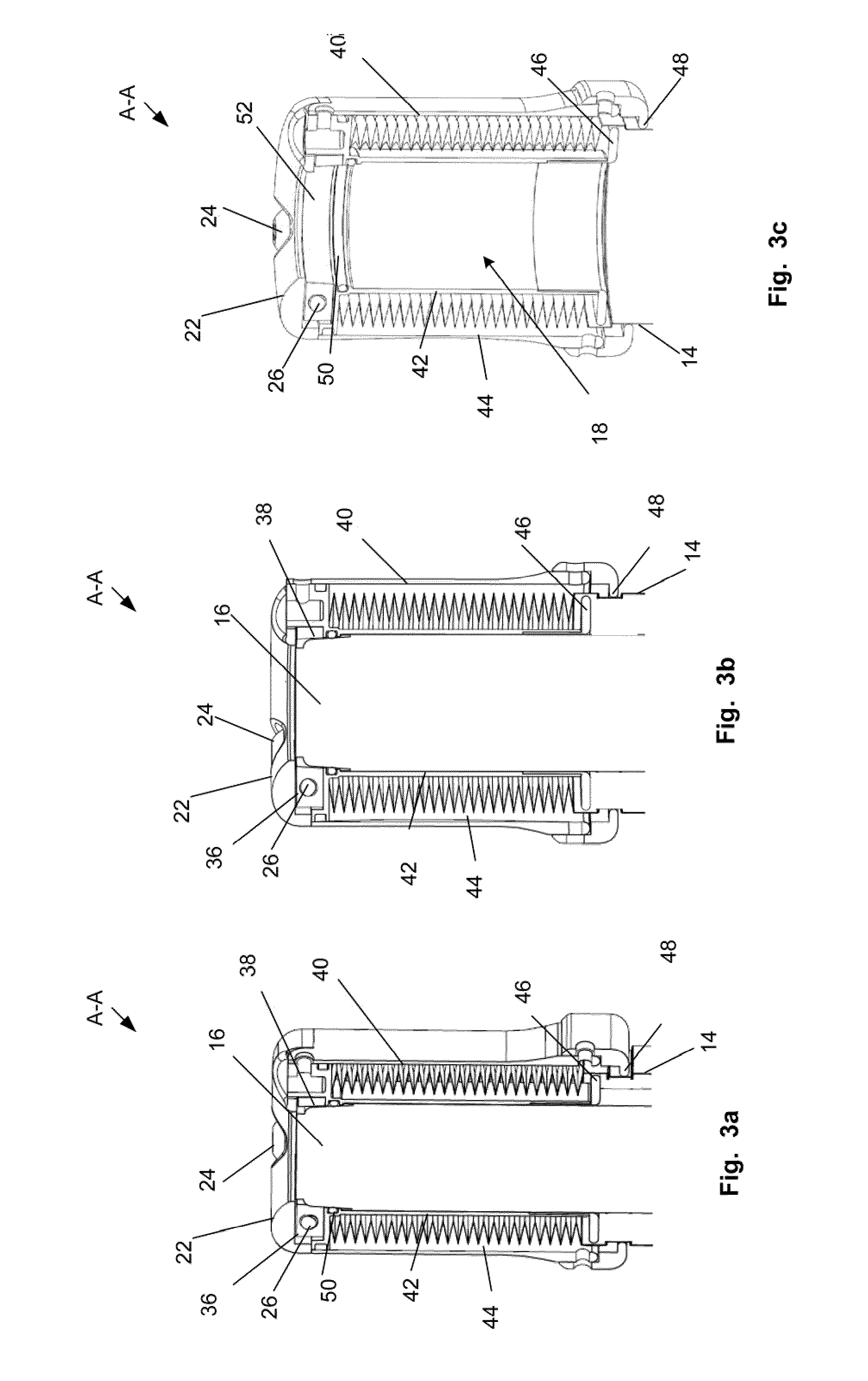
[0111]FIG. 1 illustrates a biological navigation device 10. The device can be used for navigation through a biological anatomy, such as a biological lumen, for example any or all of the GI tract (e.g., colon, stomach, esophagus) or cardiovascular vessels (e.g., arteries, veins, heart chambers).

[0112]The navigation device can be removably attached or integrated (e.g., permanently fixed, welded, glued, fused, or otherwise substantially permanently fixed) with an elongated element. The elongated element can be, for example, an endoscope or colonoscope. For example, the elongated element can be a CF-Q160 series, PCF-160 series, or CF-2T160 series colonoscope (from Olympus America, Inc., Center Valley, Pa.), a Pentax EC-series colonoscope (from Pentax of America, Inc., Montvale, N.J.), a Fujinon HD Super CCD colonoscope, or a G-5 endoscope (from Fujinon Inc., Wayne, N.J.).

[0113]The biological navigation device 10 can have a head 12, a tube 14 or a combination thereof. The head 12 can hav...


PUM


Abstract

Biological navigation devices and methods are disclosed. The devices can be used as or to support colonoscopies or endoscopes. The devices can have one or more releasable, and / or everting, and / or pressurized tubes. The devices can be removably attached to elongated elements, such as colonoscopes or other endoscopes.

Description

CROSS-REFERENCE TO RELATED APPLICATIONS[0001]This application is a continuation of prior PCT Application No. PCT / US2008 / 052535 filed 30 Jan. 2008, which claims priority to U.S. Provisional Application Ser. Nos. 60 / 887,319, filed 30 Jan. 2007; 60 / 887,323, filed 30 Jan. 2007; and 60 / 949,219, filed 11 Jul. 2007, which are all incorporated herein by reference in their entireties.BACKGROUND OF THE INVENTION[0002]1. Field of the Invention[0003]The presented invention relates generally to devices for the exploration of luminal cavities. One such device example is an endoscope, which can be used to explore body passages. Such passages typically include, but are not limited to, the GI tract, the pulmonary and gynecological systems, urological tracts, and the coronary vasculature. One application is directed towards the exploration of the lower part of the GI tract, for example the large intestine or colon.[0004]2. Description of the Related Art[0005]Colonoscopy is a diagnostic and sometimes ...

Claims


Application Information

Patent Timeline
Patent Type & Authority Applications(United States)
IPC IPC(8): A61B1/01
CPCA61B1/31A61B1/00135A61B1/0055A61B1/0051A61B1/01A61B1/00071A61M25/0133A61M25/0113A61B2017/003A61M25/0116A61B17/00234A61B1/00156A61B1/0008A61B1/005A61B1/00151
Inventor TILSON, ALEXANDER QUILLINDUVAL, GENEBARHAM, MITCHELL C.KNIGHT, DAVID P.DOWNS, ROLAND J.ADAMS, CHRISTOPHER MICHAELMORRIS, STEPHEN J.SCHEEFF, MARK CHRISTOPHER
Owner LOMA VISTA MEDICAL
Why Eureka
Try Eureka