Apparatus and methods for perivalvular leak occlusion

a technology of perivalvular leakage and apparatus, which is applied in the field of can solve the problems of perivalvular regurgitation during use, leakage about the periphery of the implanted valve, and replacement valves, so as to facilitate occlusion of perivalvular leakage, and reduce simultaneous interferen

Inactive Publication Date: 2010-08-05
MAYO FOUND FOR MEDICAL EDUCATION & RES
View PDF11 Cites 16 Cited by
  • Summary
  • Abstract
  • Description
  • Claims
  • Application Information

AI Technical Summary

Benefits of technology

[0007]In various embodiments, the flanges of the proximal and / or distal covers may preferably have noncircular perimeters to facilitate occlusion of a perivalvular defect while reducing simultaneous interference with or occlusion of the implanted replacement valve with which the apparatus is used.
[0008]In various embodiments, the proximal and / or distal covers may be rotatable about a longitudinal axis extending through the perivalvular leak. Rotation of the proximal and / or distal covers may be more beneficial if coupled with noncircular flanges to facilitate occlusion of a perivalvular defect while reducing simultaneous interference with (or occlusion of) the implanted replacement valve with which the apparatus is used.
[0010]It may be preferred that the apparatus of the present invention be compatible with conventional guide catheters, delivery catheters and imaging technology to facilitate deployment and proper positioning of the apparatus.
[0014]In some embodiments, the perivalvular leak occlusion apparatus may have a proximal hub that may include a first element, a second element and a cinching element, wherein the cinching element has an orifice through which the retention cable extends, and further wherein the cinching element is adapted for non-reversible movement in the distal direction over the retention cable, and further wherein the cinching element is adapted to retain the proximal flange in the deployment configuration. The first element and the second element may be spaced apart from each other along the retention cable when the proximal flange is in the delivery configuration, wherein the first element and the second element are closer to each other when the proximal flange is in the deployment configuration. The first element and the second element may have complementary shapes such that rotation of the first element causes corresponding rotation of the second element, wherein the proximal flange can be rotated about the retention cable. The cinching element of the proximal hub may maintain the retention cable in tension when the apparatus is in the deployed configuration.

Problems solved by technology

Although the valves may address serious deficiencies in cardiac function, the replacement valves may, as implanted, still suffer from leaks located about the periphery of the implanted valve.
A leak or leaks located about the periphery of the implanted valve typically result in perivalvular regurgitation during use.
The devices and methods disclosed may suffer from a one or more disadvantages such as, e.g., requiring inflation, requiring one or more tissue anchors that may hinder removability of the device, etc.
As such, the devices may potentially be subject to unwanted dislodgement after deployment.

Method used


Image

  • Apparatus and methods for perivalvular leak occlusion
  • Apparatus and methods for perivalvular leak occlusion
  • Apparatus and methods for perivalvular leak occlusion

Examples


Embodiment Construction

[0027]In the following description of exemplary embodiments of the invention, reference is made to the accompanying figures of the drawing which form a part hereof, and in which are shown, by way of illustration, specific exemplary embodiments in which the invention may be practiced. It is to be understood that other embodiments may be utilized and structural changes may be made without departing from the scope of the present invention.

[0028]As discussed herein, the present invention provides apparatus and methods useful in treating perivalvular leaks located around the periphery of implanted replacement valves. The location of the defect(s) may, e.g., be identified by echocardiography (intracardiac, transesophageal, transthoracic, or combination thereof) and / or invasive angiography. Both of these techniques may then be utilized adjunctively to confirm positioning of the apparatus of the invention before, during, and after deployment.

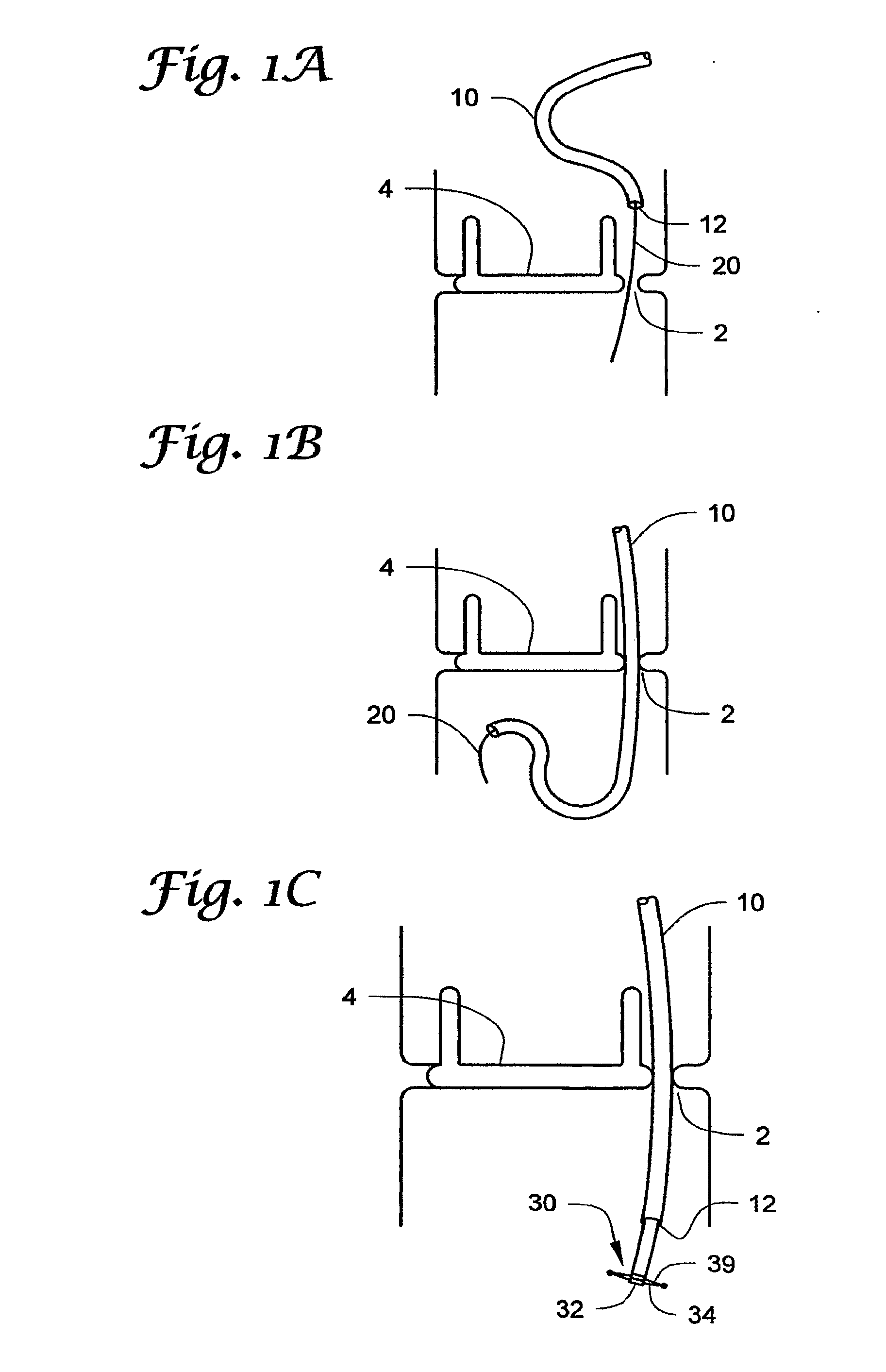
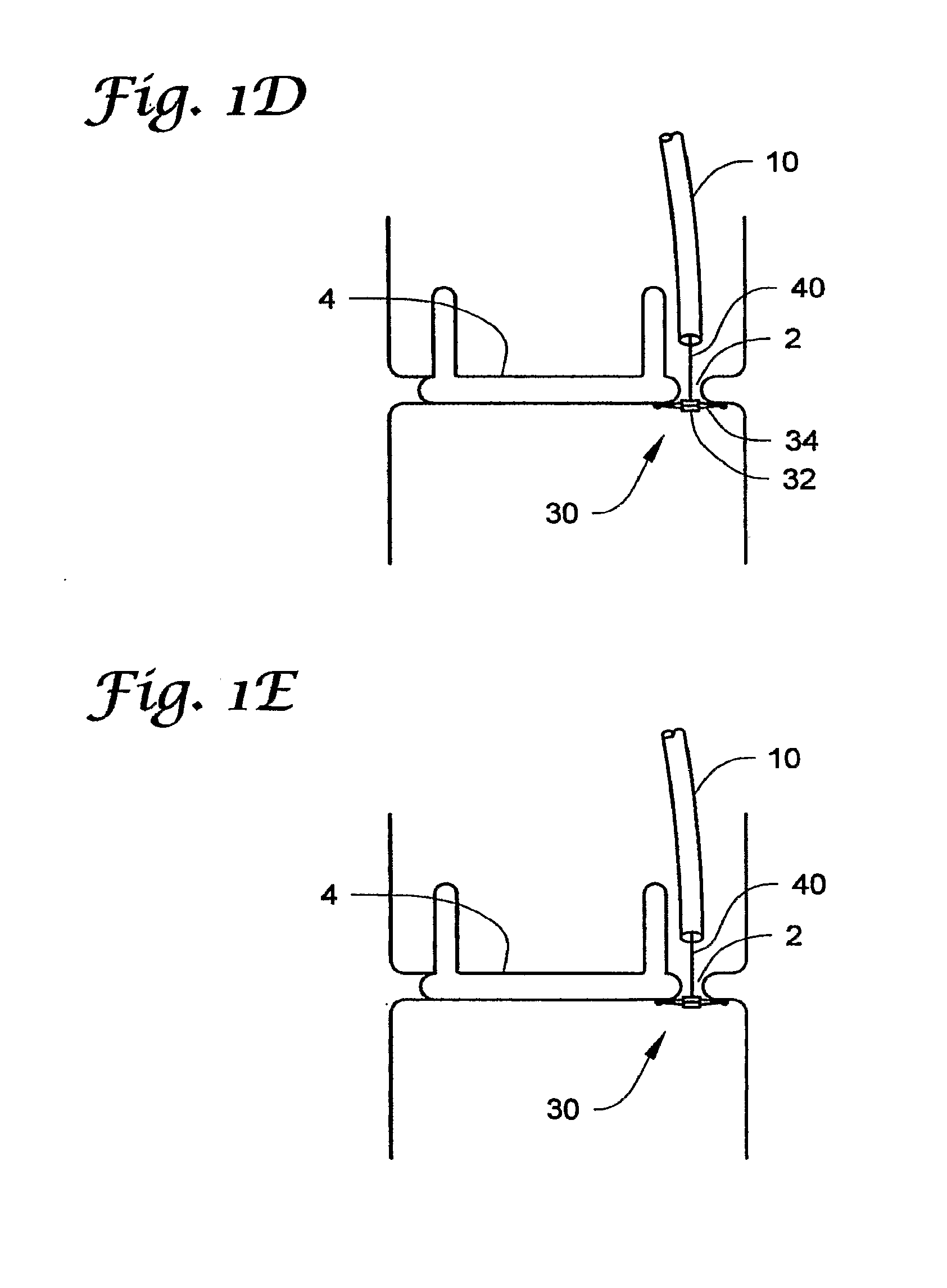
[0029]One deployment method is depicted in FIGS. ...


PUM


Abstract

Apparatus and methods for occluding perivalvular leaks located around the periphery of implanted replacement valves. The apparatus and methods may include both distal and proximal covers adapted for placement over a perivalvular leak, with the covers retained in position by tension between the proximal and distal flanges. The distal and proximal covers may be capable of collapsing into a delivery configuration amenable for delivery to an internal body location through a lumen of a delivery catheter and a deployment configuration in which a flange of the cover extends radially outward such that the flange defines a first major surface facing the opposing cover.

Description

RELATED APPLICATION[0001]The present application claims the benefit of U.S. Provisional Patent Application Ser. No. 60 / 814,820, filed on Jun. 19, 2006 and titled APPARATUS AND METHODS FOR PERIVALVULAR LEAK OCCLUSION, which is hereby incorporated by reference in its entirety.[0002]The present invention relates generally to implantable medical devices and, more particularly, to the occlusion of perivalvular leaks associated with, e.g., implanted replacement cardiac valves.[0003]Cardiac valve replacement is well known in the art. The implanted valves may include, e.g., bioprosthetic or mechanical cardiac valves located in the aortic, mitral, pulmonary, or tricuspid positions. Although the valves may address serious deficiencies in cardiac function, the replacement valves may, as implanted, still suffer from leaks located about the periphery of the implanted valve. A leak or leaks located about the periphery of the implanted valve typically result in perivalvular regurgitation during us...

Claims


Application Information

Patent Timeline
Patent Type & Authority Applications(United States)
IPC IPC(8): A61B17/12
CPCA61B17/0057A61B2017/00867A61B2017/00243
Inventor SORAJJA, PAUL
Owner MAYO FOUND FOR MEDICAL EDUCATION & RES
Why Eureka
Try Eureka