
Systems and methods for an impact location and amplitude sensor

a technology of amplitude sensor and location sensor, which is applied in the field of system and method of impact location and amplitude sensor, can solve the problems of limited use of impact sensation in devices, arrays may be overly costly for many applications, and tracking, while effective, is often uneconomical or infeasible for many applications

Inactive Publication Date: 2010-08-05
MATRIX SPORTS GROUP
View PDF13 Cites 35 Cited by
  • Summary
  • Abstract
  • Description
  • Claims
  • Application Information

AI Technical Summary

Benefits of technology

[0007]To achieve the foregoing and in accordance with the present invention, an impact location and amplitude sensor is provided. Such an impact

Problems solved by technology

Currently, the use of impact sensation in devices is typically limited by economic and logistic constraints.
Such arrays may be overly costly for many applications.
Tracking, while effective, is often uneconomical or infeasible for many applications.
Likewise, determining amplitude of impact force may be difficult via tracking methods.

Method used


Image

  • Systems and methods for an impact location and amplitude sensor
  • Systems and methods for an impact location and amplitude sensor
  • Systems and methods for an impact location and amplitude sensor

Examples


Embodiment Construction

[0032]The present invention will now be described in detail with reference to a few preferred embodiments thereof as illustrated in the accompanying drawings. In the following description, numerous specific details are set forth in order to provide a thorough understanding of the present invention. It will be apparent, however, to one skilled in the art, that the present invention may be practiced without some or all of these specific details. In other instances, well known process steps and / or structures have not been described in detail in order to not unnecessarily obscure the present invention. The features and advantages of the present invention may be better understood with reference to the drawings and discussions that follow.

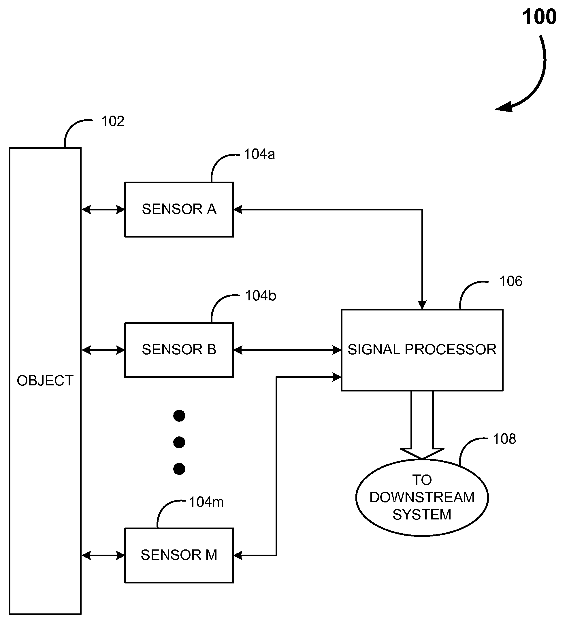
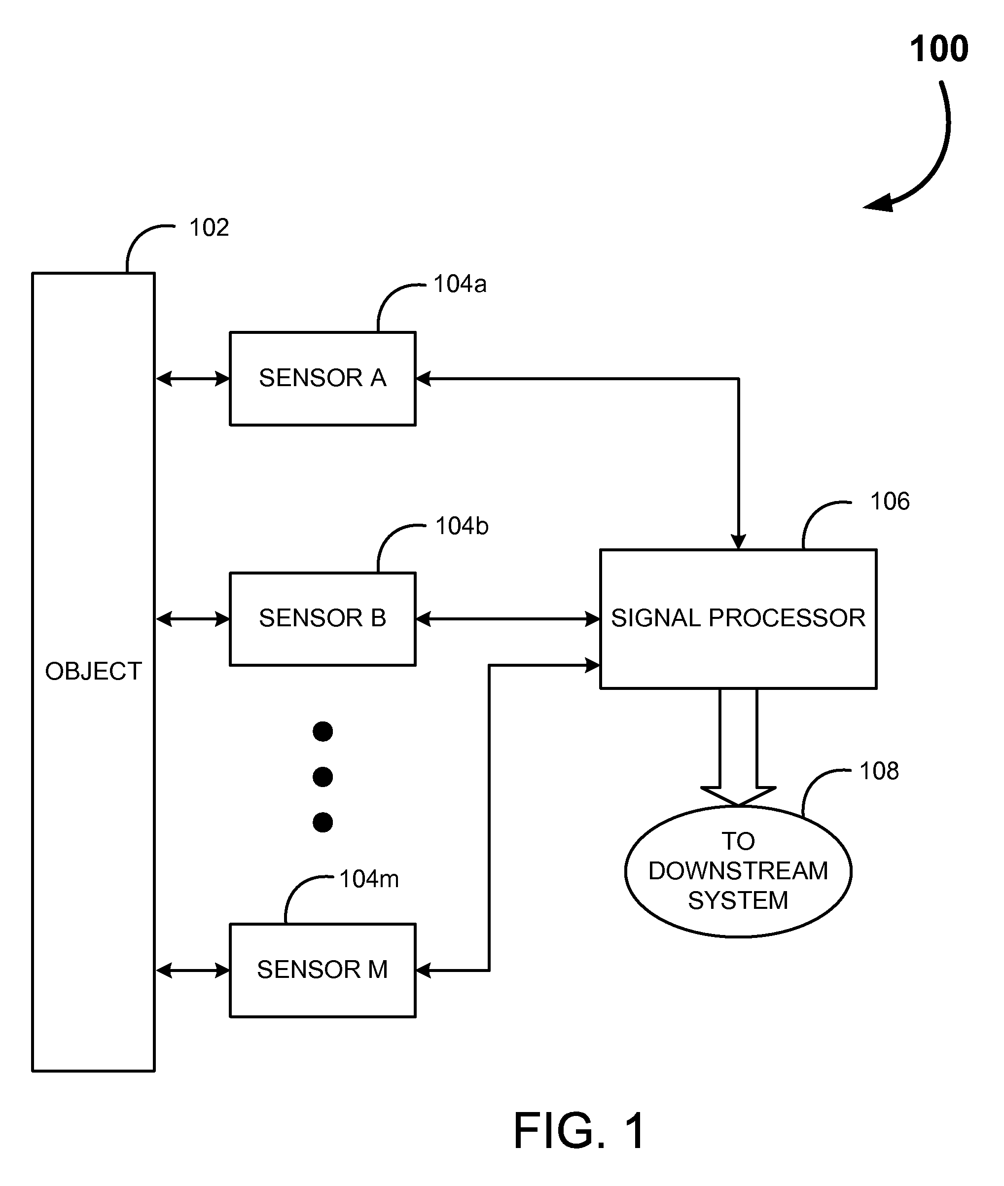
[0033]To facilitate discussion, FIG. 1 illustrates an embodiment of a block diagram of the Impact Location and Amplitude Sensory System 100. An Object 102 may be seen coupled to one or more Sensors 104a to Sensors 104a to 104m. The Object 102 may be any ...


PUM


Abstract

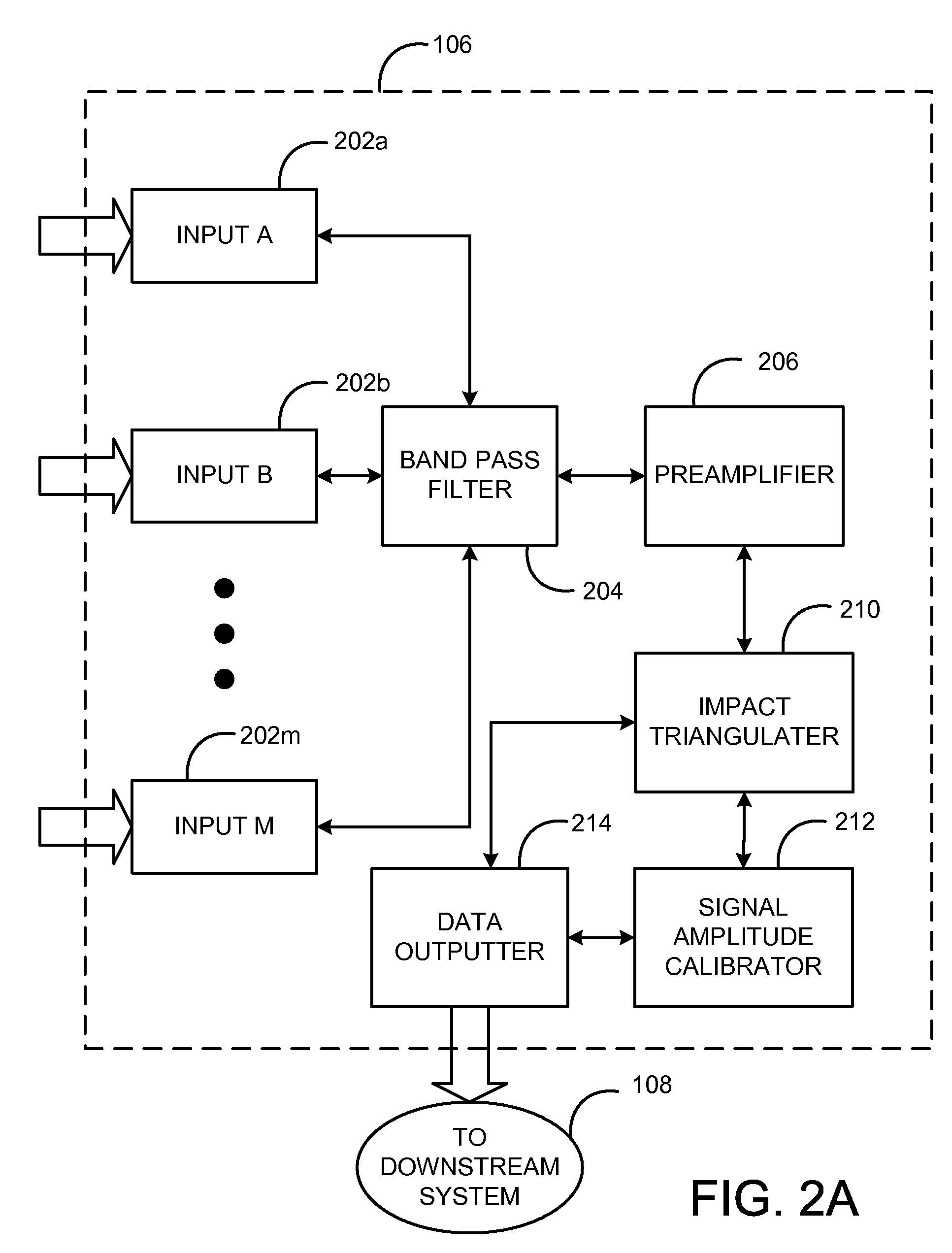
An impact location and amplitude sensory system is provided. Such an impact sensory system may be useful in conjunction with gaming, education, as a control and feedback mechanism for virtually any surface. One embodiment of the impact sensory system may include at least one sensor and a signal processor. The sensor(s) may couple to the object. Sensors may include any of microphones and accelerometers. The sensor(s) receive an impact wave from an impact to the object, either as a propagating acoustic wave or as a traverse phase shift in natural oscillation. The sensor(s) may generate an impact signal in response to the sensed impact wave. The signal processor may couple to the sensor(s). The signal processor may include a preamplifier, an impact triangulator, and an outputter. The impact triangulater may identify a location of the impact from the impact signals. The outputter may then output data regarding the location of the impact.

Description

BACKGROUND OF THE INVENTION[0001]The present invention relates to impact sensation. More particularly, the present invention relates to generating information as to the location and amplitude of an impact force.[0002]The ability to sense impacts has importance in a wide range of devices. For example, impact sensation may be used in automobiles for deployment of airbags. A computer keyboard senses impact on the keys to input text information to the computer. Likewise, most controller mechanisms, be they television equipment controllers, music keyboards or gaming controllers, require some level of impact sensation.[0003]Currently, the use of impact sensation in devices is typically limited by economic and logistic constraints. Typical impact sensory mechanisms include an array of sensors, such as the individual keys of a keyboard. Sensors which receive an impact force output a signal. The location of the sensor(s) thus indicates the location of impact. Thus, for a large impact surface...

Claims


Application Information

Patent Timeline
IPC IPC(8): G06F19/00G01L1/00G06F15/00
CPCA63B24/0021G01S11/14A63B69/002A63B69/34A63B2024/0043A63B2069/0008A63B2220/13A63B2220/40A63B2220/808A63B2220/833A63B2220/89A63F2300/1068A63F2300/8011G01S5/22A63B63/00A63B69/22A63B2244/102
Inventor MCCAULEY, JACK J.
Owner MATRIX SPORTS GROUP
Learn More