
Dynamic purge system for a heat recovery wheel

a technology of heat recovery wheel and purge system, which is applied in the direction of water supply installation, lighting and heating apparatus, heating types, etc., can solve the problems of reducing and affecting the purge performance of the purge system. achieve the effect of improving the purge performan

Active Publication Date: 2010-08-12
J&J MISSION CRITICAL LLC
View PDF15 Cites 29 Cited by
  • Summary
  • Abstract
  • Description
  • Claims
  • Application Information

AI Technical Summary

Benefits of technology

[0011]Generally, the invention is an automatic operable and dynamic purge system utilizing either a single or a double purge system that is incorporated into a heat wheel such as a Thermowheel™ heat wheel made by Thermotech Enterprises, Inc. of Tampa, Fla. For an automatically operable dynamic single purge, the system comprises two radial seals. The first seal is fixed in location on one face of the wheel and the second seal is dynamic and is on the opposite face. For the dynamic double purge, the system comprises three radial seals. Two seals are fixed in location on one face of the wheel and the third seal is dynamic and is on the opposite face. In both instances the purge directs a controlled area of supply air into the exhaust air stream passing through the heat recovery wheel. The latter configuration is called a double purge because this purge air must travel through the wheel twice, enabling improved purge performance.

Problems solved by technology

The user is able to adjust the purge angle, but it is impractical to adjust the often bolted arrangement regularly as air flow conditions change.
The fixed angle restricts system performance.
But when air flows are higher, the purge is no longer at optimum position and excessive supply air is allowed to short circuit back into the exhaust air flow without flowing through the building first.
This wastes energy and reduces cost savings to the customer.
This is not an optimal solution as thermodynamic performance is negatively affected.

Method used


Image

  • Dynamic purge system for a heat recovery wheel
  • Dynamic purge system for a heat recovery wheel
  • Dynamic purge system for a heat recovery wheel

Examples


Embodiment Construction

[0066]Referring now to the drawings, FIGS. 6-30 disclose varying embodiments of the present invention, which generally is a dynamic purge system that is incorporated into a heat recovery wheel. The system may be incorporated into the heat recovery wheel in a single purge arrangement or a double purge arrangement.

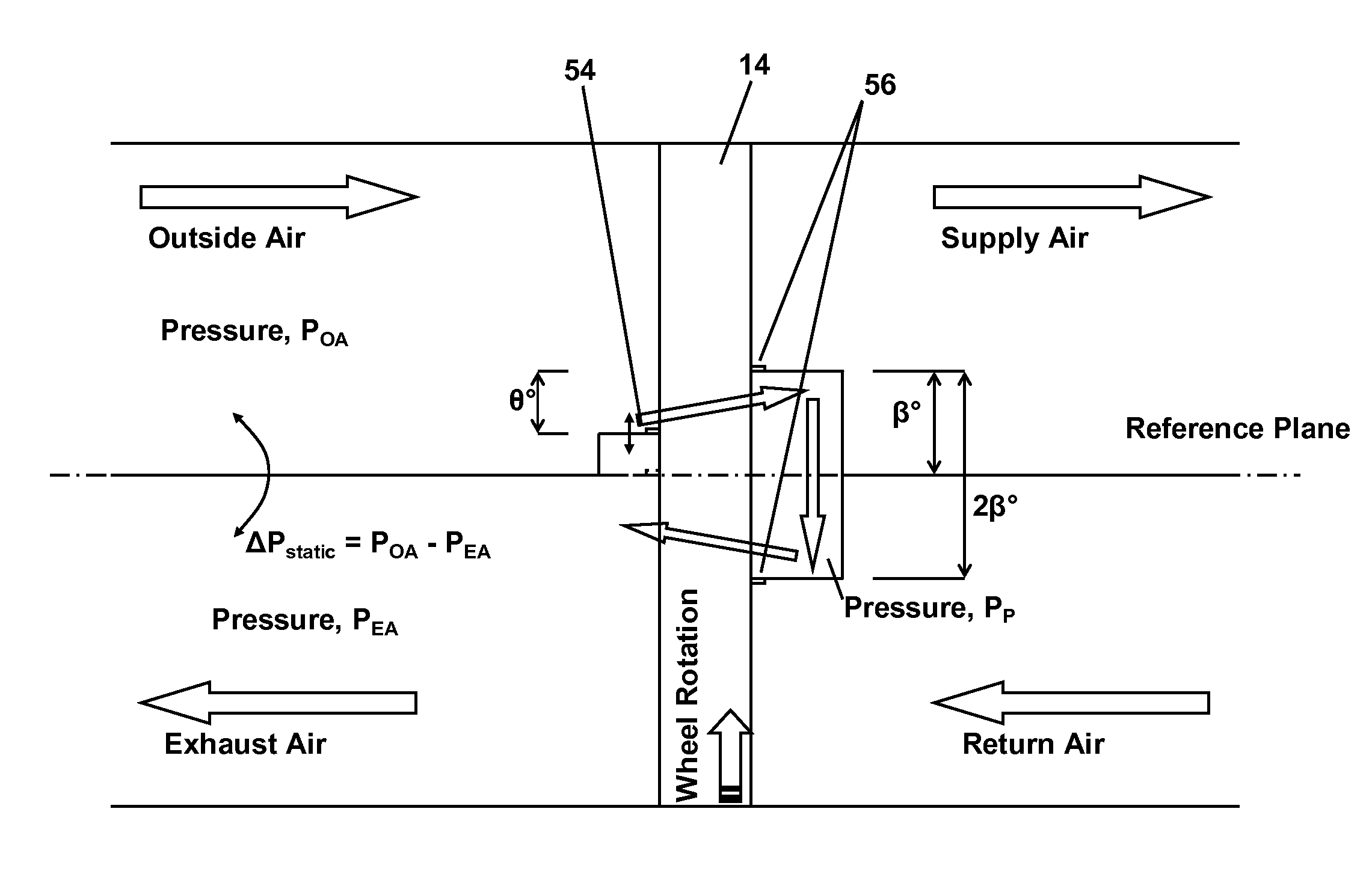
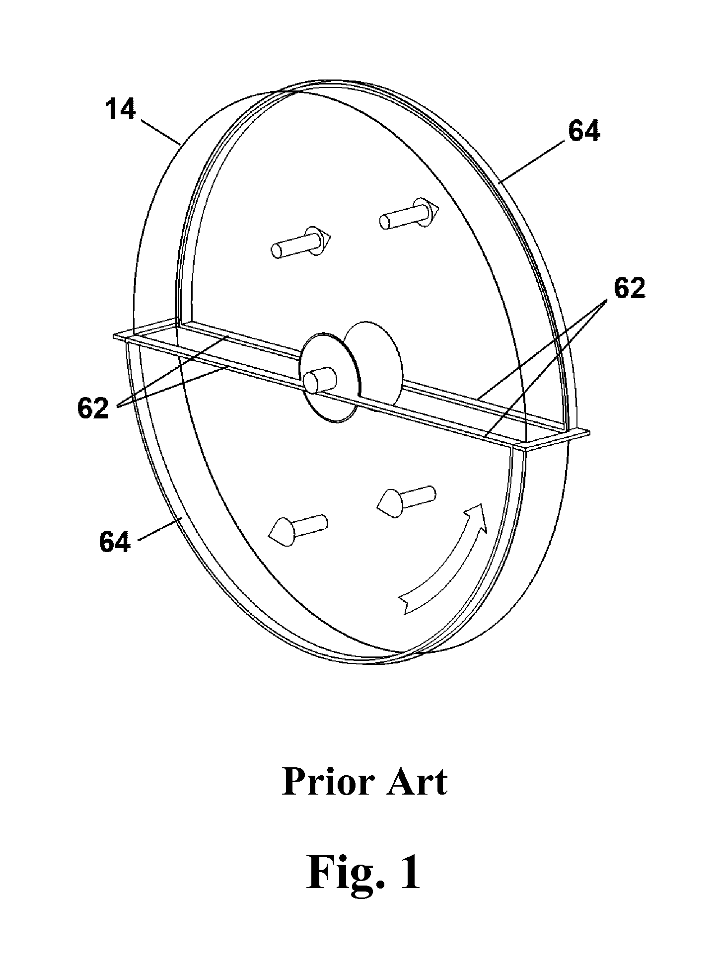
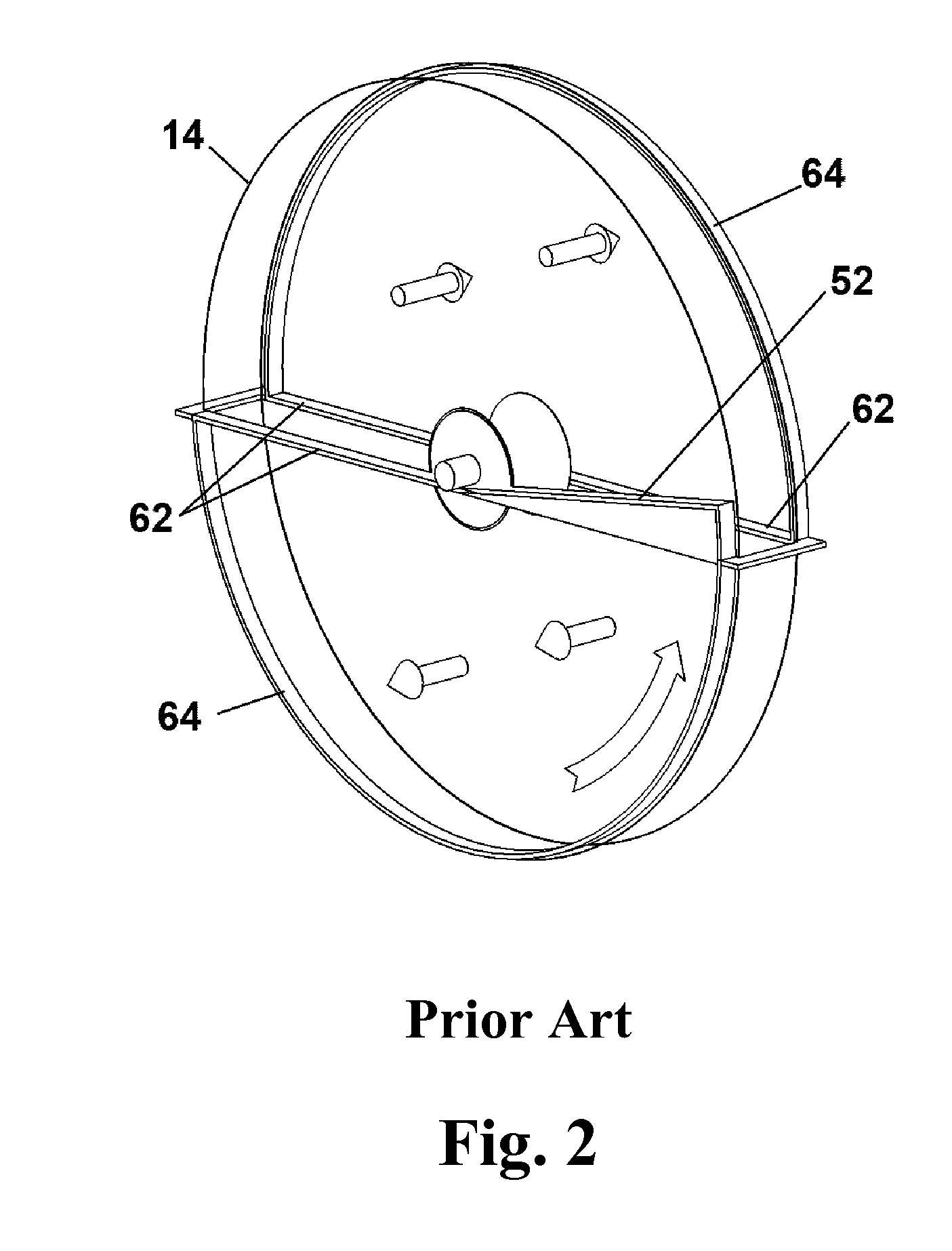
[0067]The single purge system comprises two radial seals 52,54 that direct a controlled area of supply air into the exhaust air stream passing through the heat recovery wheel. One seal 52 is fixed in location on one face of the wheel 14 and the second seal is dynamic 54 and is on the opposite face. The configuration is called a single purge because this purge air must travel through the wheel only once.

[0068]The dynamic seal 54 is secured by an automatic wiper blade 12. This wiper blade is pin jointed (or pivotally attached at 24) near the center of the wheel 14 so that it rotates, in turn, allowing the seal to rotate whilst remaining approximately radial to the wheel. The a...


PUM


Abstract

An automatically operable dynamic purge system that is incorporated into a heat recovery wheel that comprises a number of radial seals that direct a controlled area of supply air into the exhaust air stream passing through the heat recovery wheel. Two possible configurations include a single purge and a double purge. For the single purge, one seal is fixed in location on one face of the wheel and a second seal is dynamic and is on the opposite face. For the double purge, two seals are fixed in location on one face of the wheel and a third seal is dynamic and is on the opposite face. In each case the dynamic seal is secured by an automatically operable wiper blade. This wiper blade is attached near the center of the wheel such that it rotates, in turn, allowing the seal to rotate whilst remaining approximately radial to the wheel.

Description

RELATED APPLICATION[0001]This application claims the benefit of U.S. Provisional Patent Application Ser. No. 61 / 150,344 filed Feb. 6, 2009.FIELD OF THE INVENTION[0002]The invention relates to system and method for controlling heat recovery wheels in building ventilation systems.BACKGROUND OF THE INVENTION[0003]Heat wheels are used worldwide in buildings where exhausted stale or contaminated air is being exchanged with outside air. The device transfers heat and humidity between the exhaust and supply air streams by rotating between the two adjacent air streams. The wheel transfers sensible heat energy as it absorbs energy in one air stream and emits it in the other. Latent heat energy can be transferred by using a desiccant. By transferring this energy the wheel reduces the work required by an air conditioning unit, providing the owner with a cost saving. There are companies producing this product in Sweden, Japan, India and the USA.[0004]To minimize cross flow of the higher pressure...

Claims


Application Information

Patent Timeline
IPC IPC(8): F15D1/00F24F3/12
CPCF28D19/047F24F2203/104Y10T137/0318
Inventor D'ARCY, MARCUS JAMESERIKSSON, KRISTER NILS
Owner J&J MISSION CRITICAL LLC
Features
  • Generate Ideas
  • Intellectual Property
  • Life Sciences
  • Materials
  • Tech Scout
  • Unparalleled Data Quality
  • Higher Quality Content
  • 60% Fewer Hallucinations
Learn More