
Method and Apparatus for Multi-Zone Stimulation

Inactive Publication Date: 2010-08-12
HALLIBURTON ENERGY SERVICES INC
View PDF8 Cites 72 Cited by
  • Summary
  • Abstract
  • Description
  • Claims
  • Application Information

AI Technical Summary

Benefits of technology

[0031]While there are many advantages of the apparatus and methods disclosed herein, only some will be discussed or alluded to herein. One advantage of the present invention is the incorporation of several tools and methods into a single operation to allow the efficient and cost effective treatment in a high-temperature high-pressure (“HTHP”) well. In an embodiment, the use of a hydraulic workover unit may allow the workover of the HTHP well to be completed under conditions of high pressure in a safe and efficient manner. Utilizing a hydraulic workover unit may allow fluid to be transferred in and out of the well bore through both a tubing string and the annular space between the tubing and casing. In addition, the present disclosure includes methods of using the apparatus to perforate, fracture, and treat multiple formation intervals in a single trip with jointed tubing into the well bore. This may be advantageous for HTHP wells. For deep wells, a single trip with jointed tubing may take a considerable amount of time, making any workover operation with several trips in and out of the well bore expensive and inefficient. The efficiencies gained by the unique deployment of these tools may allow for an efficient replacement of tools in the event of unplanned events such as the premature failure of the tools or remediation of early screen-outs during multiple interval stimulation treatments
[0032]In an embodiment, the apparatus of the present disclosure may comprise a downhole tool system disposed on tubing string with an interchangeable set of tools for performing treatment operations.
[0033]In one embodiment, the present invention provides a downhole tool system comprising: a profile nipple disposed on a tubing string, wherein the profile nipple comprises a locking receptacle; and a tool assembly, wherein the tool assembly has a locking lug, wherein the locking lug engages the locking lug receptacle, wherein the tool assembly may be passed through the tubing string to engage the profile nipple. In some embodiments, the tool assembly comprises at least one tool selected from the group consisting of: a perforating gun, and a washing tool. In some embodiments, the tool comprises a hydrajetting tool. In some embodiments, the hydrajetting tool comprises dual check valves. In some embodiments, the tool assembly may be engaged and retrieved by a wireline, a slickline, or coiled tubing. These embodiments are discussed below.
[0034]In an embodiment, a locking device may be disposed on the end of a tubing string within a subterranean formation. A variety of tools utilizing locking lugs for engaging the locking device may be used to treat the formation by passing the tools through the interior of the tubing string until they lockingly engage the locking device on the end of the tubing string. In an embodiment, a hydraulic workover unit may be utilized to allow the treatment operations to proceed while the well is under pressure. The downhole tool system and the various tools that may be used are described in more detail below.
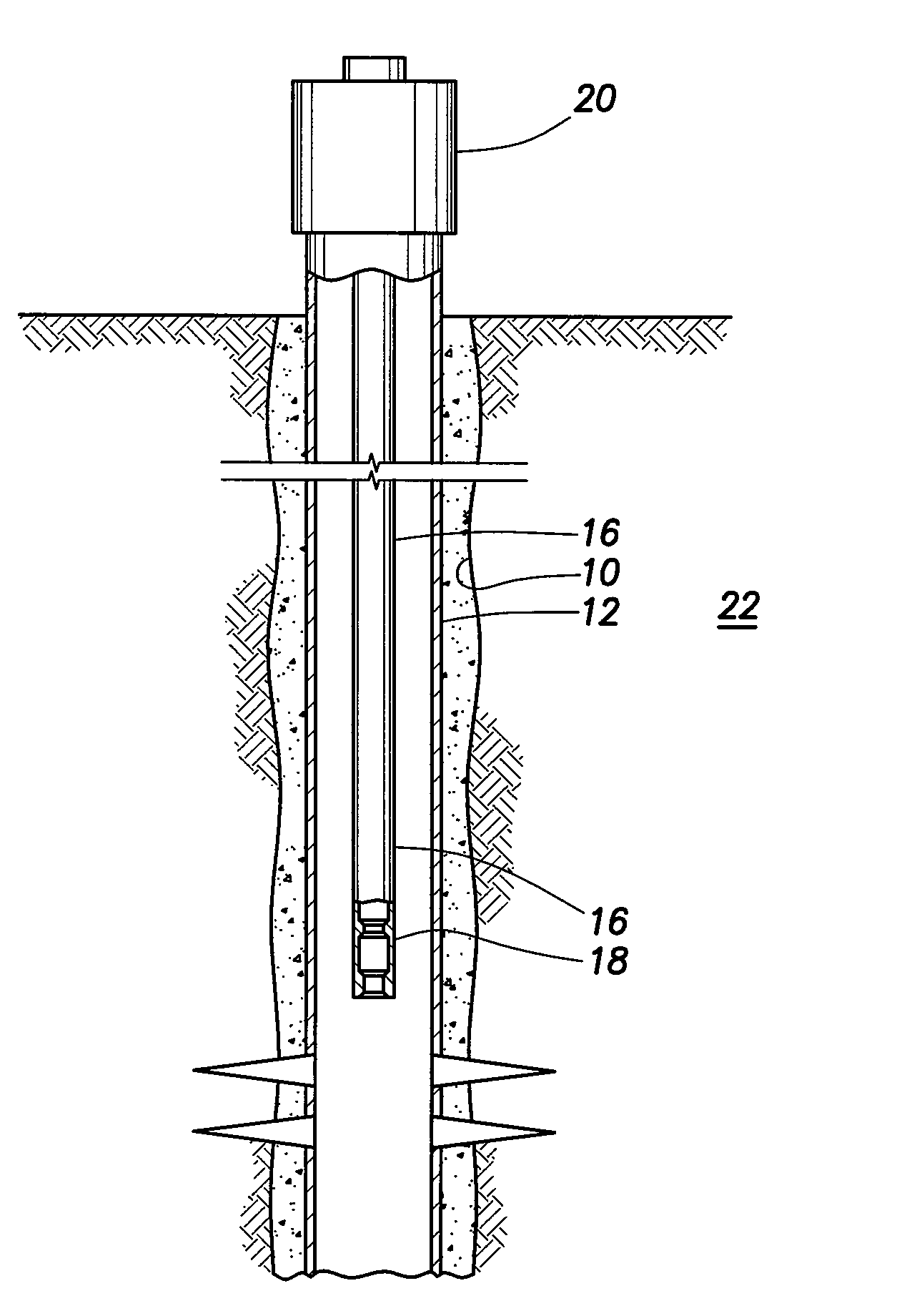
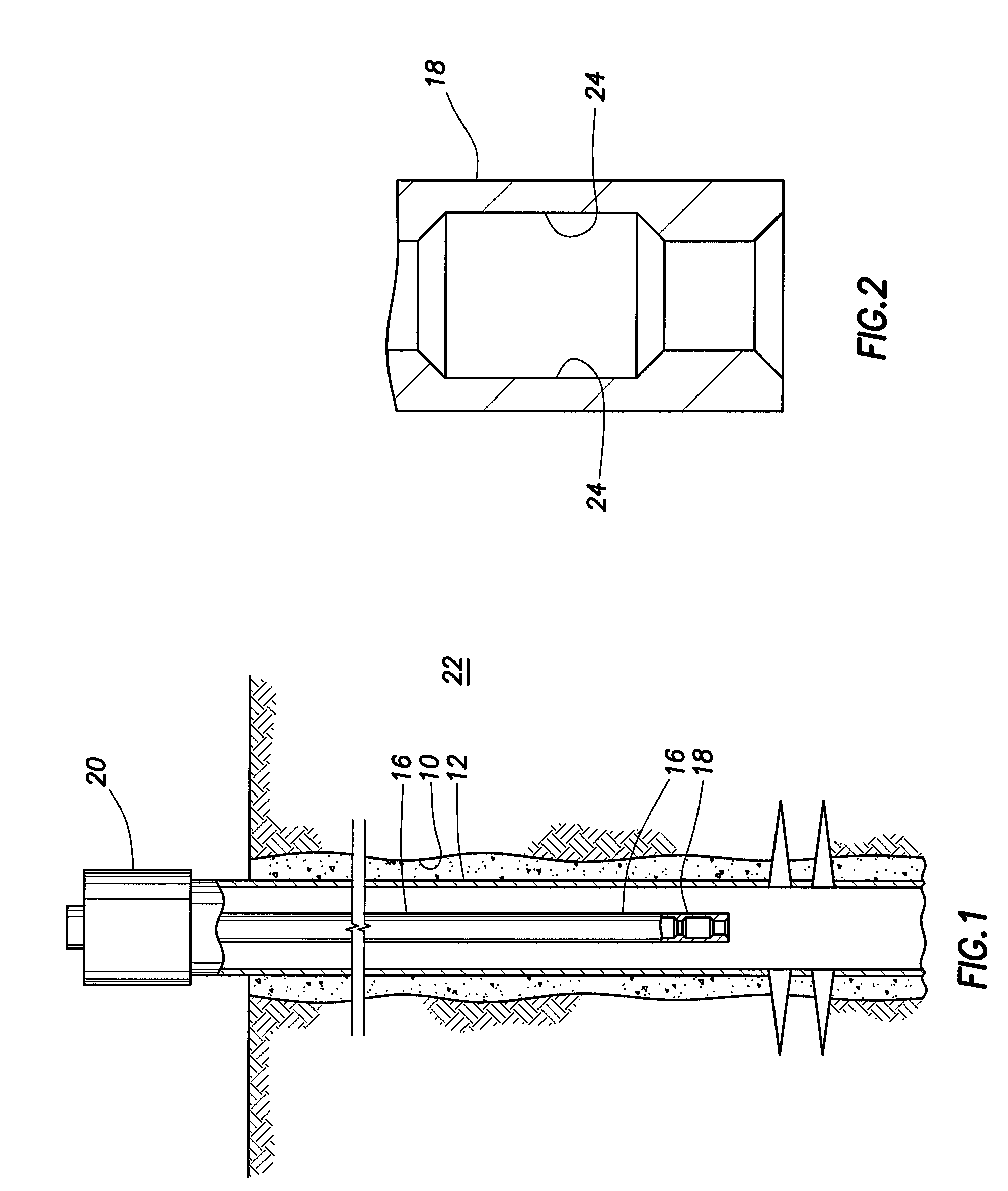
[0035]In an embodiment, the apparatus of the present disclosure may be used in a well bore disposed in a subterranean formation. In an embodiment shown in FIG. 1, a well bore 10 may be created so as to extend into a subterranean formation 22. A casing 12 may be disposed within the well bore and cement 14 may be introduced between the casing 12 and the well bore 10 walls in order to hold the casing 12 in place and prevent the migration of fluids between the casing 12 and the well bore 10 walls. A tubing string 16 may be disposed within the casing 12. In an embodiment, the tubing string 16 may be jointed tubing, coiled tubing, or any other type of tubing suitable for use in a subterranean well environment. Suitable types of tubing and an appropriate choice of tubing diameter and thickness may be known to one skilled in the art, considering factors such as well depth, pressure, temperature, chemical environment, and suitability for its intended use. In an embodiment, a hydraulic workover unit 20 may be disposed at or near the top of the tubing string 16, the casing 12, or both. The hydraulic workover unit 20 may allow for tubing and other items to be introduced into the well bore 10 while a pressure exists and is maintained within the well bore 10 and tubing string 16. The existence of a pressure within the well bore may be referred to as a live well condition.
[0036]In an embodiment shown in FIG. 2, the end of the tubing string 16 may contain a locking device that may allow a connection with a tool. In an embodiment, the locking device may be a profile nipple 18. The profile nipple 18 may be designed to allow a variety of tools to be connected to the tubing string such that they may lock into a locking receptacle 24 on the profile nipple 10. In this embodiment, the variety of tools may be passed through the tubing string until locking lugs on the tools lockingly engage the locking receptacles 24 on the profile nipple. The tool may then be utilized on the end of the tubing string to perform a treatment operation. While the terms locking receptacle and locking lugs are used herein, the tools may engage the tubing string using any type of locking device and should not be limited to locking devices with lugs. As used herein, the term locking lugs refers to any device capable of providing a temporary fixed relationship between a tool and tubing. The locking lugs can be released from their temporary fixed relationship through manipulation with a retrieving device on slickline, wireline, coiled tubing, or through the exertion of a physical force on the locking lugs such as pressure in the tubing or a set down force on the tool itself.

Problems solved by technology

Certain subterranean formations, however, have properties that may make stimulation operations difficult, time consuming, and / or expensive.
For example, high-temperature high-pressure (“HTHP”) wells may present operating difficulties.
For these deep wells, a single trip with jointed tubing may take a considerable amount of time, making any workover operation with several trips in and out of the well bore expensive and inefficient.
This is particularly inefficient when multiple intervals in a well are to be perforated and stimulated separately.

Method used


Image

  • Method and Apparatus for Multi-Zone Stimulation
  • Method and Apparatus for Multi-Zone Stimulation
  • Method and Apparatus for Multi-Zone Stimulation

Examples


example 1

[0071]In order to demonstrate the methods disclosed herein, a set of tests were conducted in Michigan in multiple shallow, low pressure, substantially vertical wells. In these tests, a hydrajetting tool was deployed from surface through a tubing string. The end of the tubing was placed at a depth corresponding to the target interval for perforating and fracturing. The end of the tubing contained a seat (e.g., a profile nipple) to prevent the hydra-jetting tool from passing completely through the end of tubing while allowing the hydra-jetting tool to have the jets exposed to the casing. The hydra-jetting tool was placed in the tubing and allowed to pass through the tubing until it was disposed in the end of tubing, where it engaged the seat. The hydra-jetting tool was engaged to form perforations in the casing. Once the perforations were formed, the fluid in the well was reverse circulated (i.e., fluid was pumped down the annulus between the casing and the tubing string to return to ...

example 2

[0073]In order to demonstrate the methods disclosed herein, another set of tests were conducted in Michigan in multiple shallow, low pressure, substantially vertical wells. These tests were substantially similar to those tests described in Example 1 with the exception that a retrievable bridge plug was used between target zones rather than the placement of one or more sand plugs.

[0074]In these tests, a hydra-jetting tool was deployed from surface through a tubing string. The end of the tubing was placed at a depth corresponding to the target interval for perforating and fracturing. The end of the tubing contained a seat (e.g., a profile nipple) to prevent the hydra-jetting tool from passing completely through the end of tubing while allowing the hydra-jetting tool to have the jets exposed to the casing. The hydra-jetting tool was placed in the tubing and allowed to pass through the tubing until it was disposed in the end of tubing, where it engaged the seat. The hydra-jetting tool w...


PUM


Abstract

Methods of treating a well bore in a single trip are provided. A tubing string may be inserted into a subterranean formation having a well bore, where the tubing string has a locking device on an end. A workover tool may be positioned in a first zone of the subterranean formation, where the workover tool engages the locking device. One or more perforations may be created or enhanced in a first zone of a subterranean formation using the workover tool, and the tubing string may be positioned in a second zone of the subterranean formation. A fracturing fluid may be introduced into the first zone of the subterranean formation at a rate and pressure sufficient to create or enhance one or more fractures in the subterranean formation. The first zone of the subterranean formation may be isolated from the second zone of the subterranean formation and one or more perforations in the second zone of the subterranean formation may be created or enhanced using the workover tool.

Description

BACKGROUND OF THE INVENTION[0001]The present invention relates to stimulation of subterranean formations, and more particularly, to a novel apparatus and methods of multi-zone stimulation of subterranean formations, in particular, at least in some embodiments, in high temperature, high pressure wells.[0002]Treatment fluids may be used in a variety of subterranean treatments, including, but not limited to, stimulation treatments and sand control treatments. As used herein, the term “treatment,” or “treating,” refers to any subterranean operation that uses a fluid in conjunction with a desired function and / or for a desired purpose. The term “treatment,” or “treating,” does not imply any particular action by the fluid or any particular component thereof.[0003]One common production stimulation operation that employs a treatment fluid is hydraulic fracturing. Hydraulic fracturing operations generally involve pumping a treatment fluid (e.g., a fracturing fluid) into a well bore that penet...

Claims


Application Information

Patent Timeline
IPC IPC(8): E21B43/247E21B33/12
CPCE21B23/08E21B43/267E21B43/11
Inventor EAST, JR., LOYDMORRISON, DANSTANOJCIC, MILORADCOURVILLE, PERRY
Owner HALLIBURTON ENERGY SERVICES INC
Learn More