
Group scanning circuit and method for a capacitive touch sensor

a capacitive touch sensor and scanning circuit technology, applied in the field of capacitive touch sensors, can solve the problem that the sequence scanning process needs a very long overall scanning time to complete the scanning of all traces, and achieve the effect of accurate positioning of the touch poin

Inactive Publication Date: 2010-08-12
ELAN MICROELECTRONICS CORPORATION
View PDF11 Cites 33 Cited by
  • Summary
  • Abstract
  • Description
  • Claims
  • Application Information

AI Technical Summary

Benefits of technology

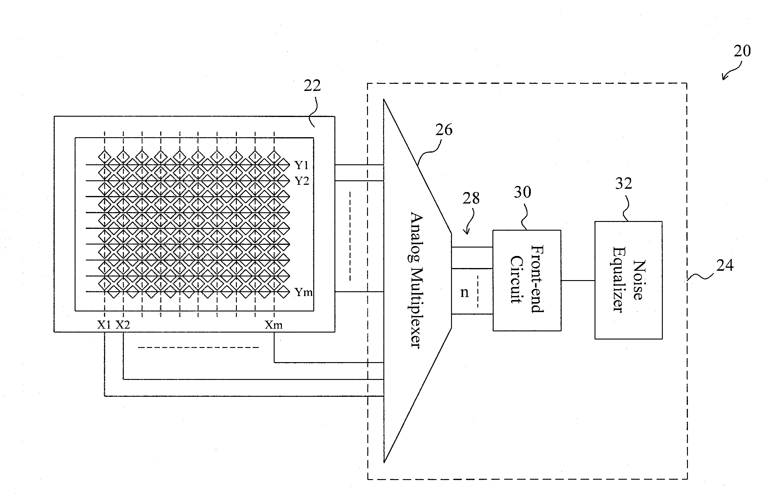
The present invention provides a circuit and method for scanning the traces of a capacitive touch sensor. The circuit includes a multiplexer and front-end circuit with several channels between them. The scanning process involves a two-step group scan where the multiplexer selects a group of traces to connect to the channels each time for simultaneous extraction of ADC values. After scanning all the traces, the touch point and the target trace with the highest ADC value are detected. A new group of traces including several traces adjacent to the target trace are then selected for further scanning to accurately position the touch point. This invention allows for more accurate touch sensing.

Problems solved by technology

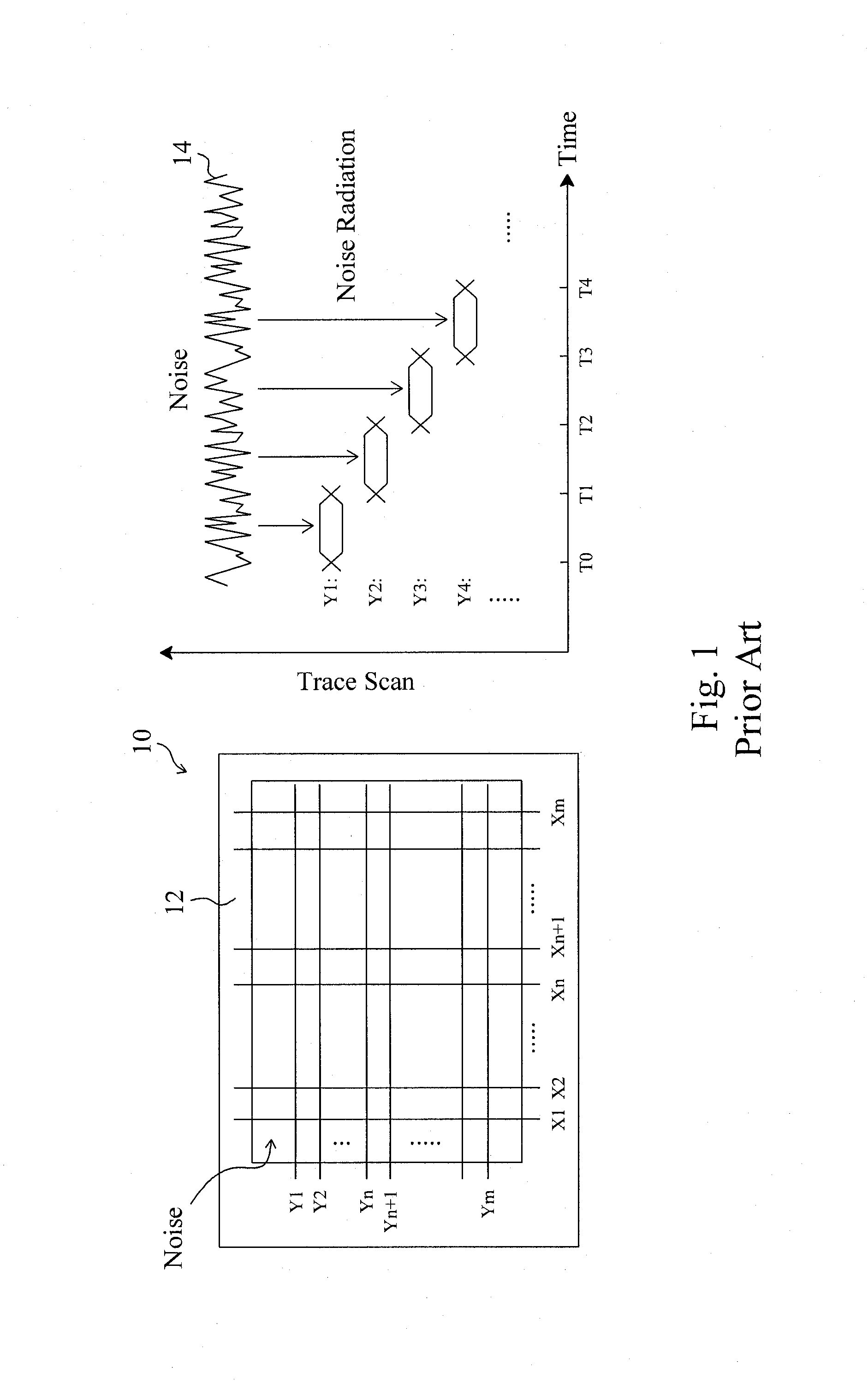
However, for a large size touch panel, the sequential scanning process needs a very long overall scanning time for completing the scanning of all the traces.

Method used


Image

  • Group scanning circuit and method for a capacitive touch sensor
  • Group scanning circuit and method for a capacitive touch sensor
  • Group scanning circuit and method for a capacitive touch sensor

Examples


Embodiment Construction

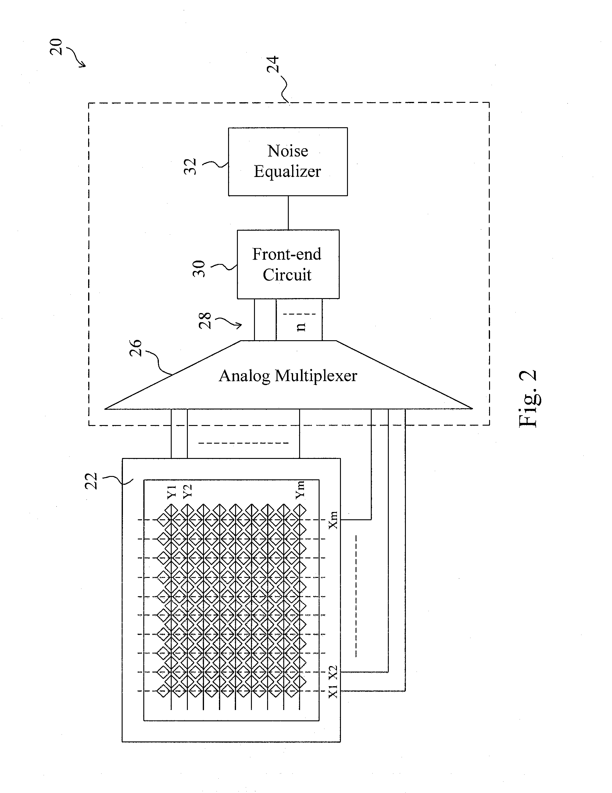
[0014]As shown in FIG. 2, a capacitive touch sensor 20 according to the present invention includes a substrate 22 with traces X1-Xm and Y1-Ym printed thereon, and a touch controller 24 connected to the traces X1-Xm and Y1-Ym. The substrate 22 may be a glass plate, a plastic membrane, or a printed circuit board (PCB), and the traces X1-Xm and Y1-Ym are patterns made of metal, indium-tin oxide (ITO) film, or other conductive materials. In the touch controller 24, an analog multiplexer 26 is connected to the traces X1-Xm and Y1-Ym such that it may select a group of traces from the traces X1-Xm and Y1-Ym to connect to n channels 28 at a time, where n is a positive integer, for a front-end circuit 30 to simultaneously detect the selected traces through the n channels 28 to extract ADC values therefrom, and a noise equalizer carries out noise equalization for the ADC values sent from the front-end circuit 30.

[0015]A process of scanning the traces X1-Xm and Y1-Ym of the capacitive touch se...


PUM


Abstract

For object detection, a two-step group scan to the traces of a capacitive touch sensor is performed, thereby dramatically shortening the overall scanning time and reducing noise effect. After all the traces are scanned by the pre-scan step to find out the trace of a touch point, the trace of the touch point and traces adjacent thereto are scanned by the re-scan step for more accurate positioning of the touch point.

Description

FIELD OF THE INVENTION[0001]The present invention is related generally to a capacitive touch sensor and, more particularly, to a group scanning touch circuit and method for a capacitive touch sensor.BACKGROUND OF THE INVENTION[0002]For object detection, conventionally, a capacitive touch sensor sequentially scans all the traces one by one from the first trace to the last trace, as shown in FIG. 1. As shown in the left part of FIG. 1, a capacitive touch sensor 10 includes a substrate 12 and traces X1-Xm and Y1-Ym printed thereon. The substrate 12 may be a glass plate, a plastic membrane, or a printed circuit board (PCB), and the traces X1-Xm and Y1-Ym are patterns made of metal, indium-tin oxide (ITO) film, or other conductive materials. As shown in the right part of FIG. 1, the capacitive touch sensor 10 will scan the traces X1-Xm and Y1-Ym one by one, each time when it performs a scanning process for object detection. For example, during the time period of T0-T1, only the trace Y1 ...

Claims


Application Information

Patent Timeline
Patent Type & Authority Applications(United States)
IPC IPC(8): G06K11/06
CPCG06F3/044G06F3/0416G06F3/041661G06F3/0446
Inventor YEH, I-HAULIN, CHUN-YU
Owner ELAN MICROELECTRONICS CORPORATION
Learn More