Overrunning coupling and control assembly including apparatus having a latching mechanism

a technology of overrunning coupling and control assembly, which is applied in the direction of clutches, non-mechanically actuated clutches, freewheel clutches, etc., can solve the problems of one-way clutches that may inadvertently change, clutch failure, etc., and achieve the effect of improving overrunning coupling and control

Active Publication Date: 2010-08-12
MEANS IND INC
View PDF26 Cites 105 Cited by
  • Summary
  • Abstract
  • Description
  • Claims
  • Application Information

AI Technical Summary

Benefits of technology

[0015]An object of at least one embodiment of the present invention is to provide an improve

Problems solved by technology

One problem associated with such controllable one-way coupling assemblies is that the one-way clutch may inadvertently change (such as due to parasitic losses) from its overrun position or mode to

Method used


Image

  • Overrunning coupling and control assembly including apparatus having a latching mechanism
  • Overrunning coupling and control assembly including apparatus having a latching mechanism
  • Overrunning coupling and control assembly including apparatus having a latching mechanism

Examples


Embodiment Construction

)

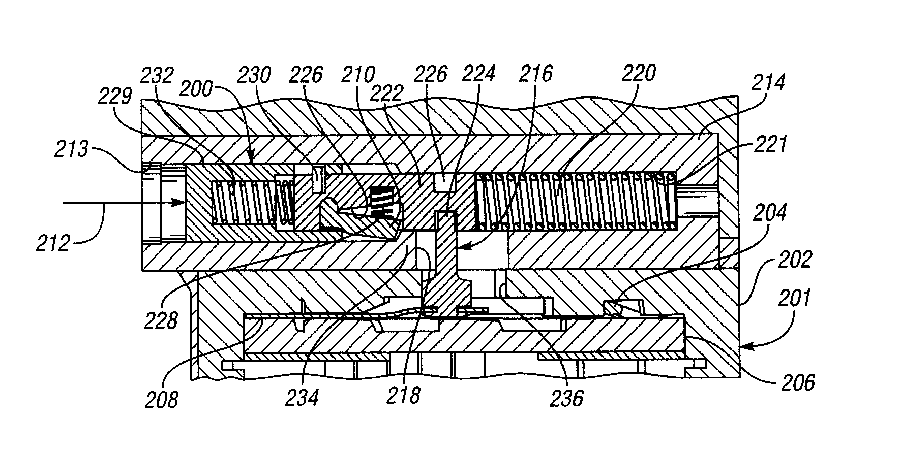
[0051]Referring now to FIGS. 6-12c, there are illustrated various embodiments of a control apparatus for use in an overrunning coupling and control assembly. In general, the control apparatus controls an overrunning coupling assembly having a first member or plate with a first surface, a second member or plate with a second surface and a control element or plate mounted for controlled shifting movement between the surfaces. The coupling assembly also has an actuator arm or pin coupled to the control element to shift the control element along a shift direction from a first or overrun position which corresponds to a first or overrun mode of the coupling assembly to a second or locked position which corresponds to a second or locked mode of the coupling assembly and then back to the first position. Because the shift direction is typically only slightly curved, the shift direction may also be referred to herein as a “shift axis”.

[0052]The apparatus generally includes a housing having a...


PUM


Abstract

Overrunning coupling and control assemblies, each of which includes control apparatus having a latching mechanism are provided. Each latching mechanism prevents an actuator arm of an overrunning coupling assembly from moving in a first direction substantially parallel to a shift direction of a control plate of the coupling assembly within a housing slot in a locked condition of the mechanism in a first position of the control plate. A control pressure signal within a bore of the housing changes the condition of the latching mechanism from locked to unlocked to unlock the actuator arm and causes the unlocked actuator arm to move along the first direction within the slot and the control element to move along the shift direction to a second position. The control pressure signal also causes a piston which has a groove formed in its outer surface to receive and retain a free end portion of the actuator arm to slide within the bore in the housing against the biasing force of the at least one biasing member. In the absence of a control pressure signal, the at least one biasing member moves the piston and thereby the unlocked actuator arm in a second direction opposite the first direction within the slot and the control element along the shift direction from the second position back to the first position and changes the condition of the latching mechanism from unlocked to locked to lock the actuator arm.

Description

CROSS-REFERENCE TO RELATED APPLICATION[0001]This application claims the benefit of U.S. provisional application Ser. No. 61 / 206,972 filed Feb. 6, 2009.BACKGROUND OF THE INVENTION[0002]1. Field of the Invention[0003]This invention relates to overrunning coupling and control assemblies, each of which includes apparatus having a latching mechanism.[0004]2. Background Art[0005]One-way clutches are commonly employed in automatic transmissions for automobiles. A one-way clutch allows a first clutch plate to free-wheel in a first rotational direction relative to a second clutch plate, and to clutch in a second rotational direction. Examples include roller clutches and sprag clutches.[0006]It may be desirable to have the one-way clutching mode operable only upon demand, such that it is in free-wheeling mode in both directions until the one-way clutching is selectively actuated. There are different means of selecting when the free-wheeling stops and one-way clutching begins.[0007]U.S. Pat. N...

Claims


Application Information

Patent Timeline
IPC IPC(8): F16D41/02
CPCF16D41/12F16D25/088F16D41/125
Inventor EISENGRUBER, GREGORY M.HENDRICK, TERRY O.HOPPE, JEFFREY C.FETTING, ROBERT D.BUKOFFOSKY, JOSHUA A.
Owner MEANS IND INC
Why Eureka
Try Eureka