Device for attaching a lift member to the fuselage of an aircraft

a technology for attaching a lift member and an aircraft fuselage, which is applied in the direction of fuselages, springs/dampers, rubber-like materials, etc., can solve the problems of unoptimized weight of such an assembly, complex fastening of half-airfoils, and greatly complicating the manufacture of fuselages. , to achieve the effect of facilitating assembly and reducing the cost of manufacturing an aircra

a technology for attaching a lift member and an aircraft fuselage, which is applied in the direction of fuselages, springs/dampers, rubber-like materials, etc., can solve the problems of unoptimized weight of such an assembly, complex fastening of half-airfoils, and greatly complicating the manufacture of fuselages. , to achieve the effect of facilitating assembly and reducing the cost of manufacturing an aircra

US20100200691A1Inactive Publication Date: 2010-08-12AIRBUS OPERATIONS (SAS)

Image

  • Device for attaching a lift member to the fuselage of an aircraft
  • Device for attaching a lift member to the fuselage of an aircraft
  • Device for attaching a lift member to the fuselage of an aircraft

Examples


Embodiment Construction

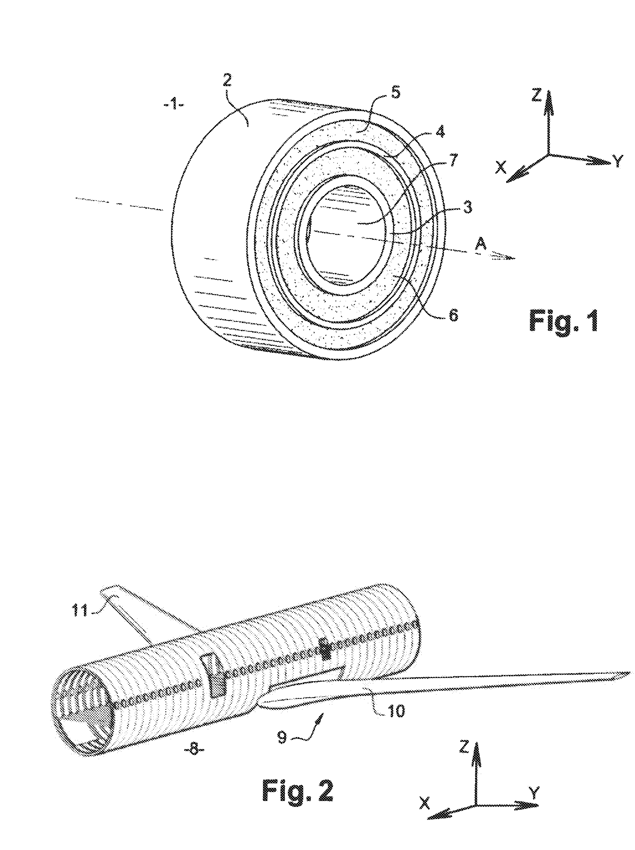
[0027]FIG. 1 shows an example of an elastic joint 1 that can be used in the fastening device according to the disclosed embodiments.

[0028]The elastic joint 1 has an external collar 2, an internal collar 3, and a sheet 4 intercalated between the two collars 2, 3, to form three concentric tubes. A first layer of elastomer 5 extends between the external collar 2 and the sheet 4, and a second layer of elastomer 6 extends between the intermediate sheet 4 and the internal collar 3. Of course it is also possible if needed to use an elastic link 1 containing no sheet 4 or having multiple sheets 4 intercalated between the external collar 2 and the internal collar 3.

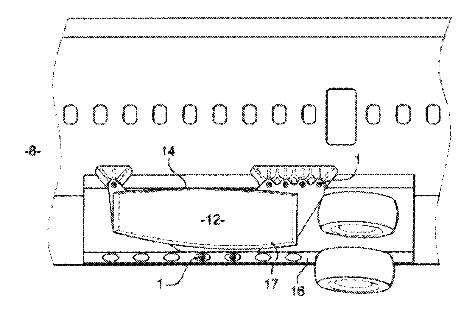
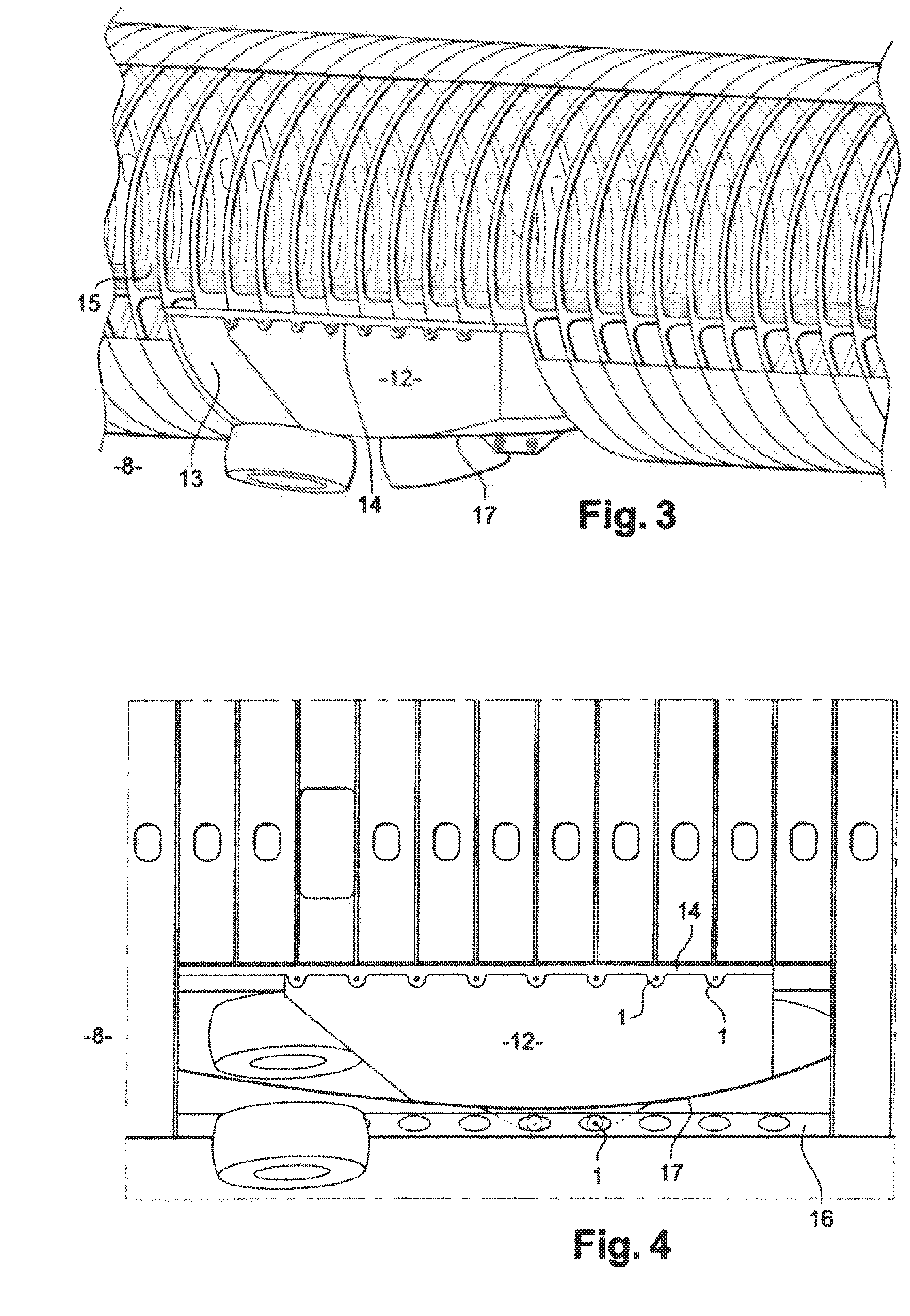
[0029]It is advantageous, as shown in FIGS. 6 and 7, for the articulated links 1 to be oriented in the fastening device so that the longitudinal axis A of the elastic link 1 extends along the Y axis of the aircraft frame of reference, so that the articulated linkage obtained between the support element and the fuselage can permit ...


PUM


Abstract

The disclosed embodiments relate to an aircraft equipped with at least one device for attaching a lift member to the fuselage which includes elastic articulations whose rigidity in translation and in rotation can be adjusted axially, vertically, and transversely. An airfoil may be connected to the body of the fuselage by these elastic articulations.

Description

[0001]This application is the National stage of International Application PCT / FR2008 / 050668, International Filing Date 15 Apr. 2008, which designated the United States of America, and which International Application was published under PCT Article 21 (s) as WO Publication 2008 / 145892 A1 and which claims priority from, and the benefit of French Application No. 07 54529 filed on 17 Apr. 2007, the disclosures of which are incorporated herein by reference in their entireties.BACKGROUND[0002]The disclosed embodiments relate to a linkage between at least one support element and an aircraft fuselage. A support element means a supporting surface such as the airfoil or a horizontal fin of the aircraft. More precisely, the disclosed embodiments relate to a device for fastening such a support element to the fuselage structure of the aircraft.[0003]In flight, the aircraft is subjected to various aerodynamic stresses that have repercussions on both the airfoil and on the fuselage and the linkage...

Claims


Application Information

Patent Timeline
12 Aug 2010
Publication
US20100200691A1
IPC
B64C1/26
CPC
B64C1/068; F16F1/38; B64C1/26
Inventors
GALLANT, GUILLAUME