Low- voltage dual power loop device and method

a dual-power loop, low-voltage technology, applied in emergency power supply arrangements, dc source parallel operation, electrical equipment, etc., can solve the problems of hard to estimate economic losses, high cost of electronic system equipment, and loss of all industries and sectors, so as to avoid loss of important data, prevent high current, and avoid heavy economic losses

Inactive Publication Date: 2010-08-12
MOXA INC
View PDF4 Cites 10 Cited by
  • Summary
  • Abstract
  • Description
  • Claims
  • Application Information

AI Technical Summary

Benefits of technology

[0011]The primary objective of the present invention is to enable respective input from the first and second power supplies to a dual power control loop which includes the first and second control chips inside. The first and second control chips are connected with a power detection loop, a power comparison loop and a power switch loop respectively, where the first and second control chips detect the priority of the first and second power supplies by using the power detection loop. When there is a power outage with the power supply of the first priority, the voltages of the power supplies of the first and second priorities can be compared by using the power comparison loop. And then the power switch loop will be used to switch over from the power supply of the first priority to the standby power supply of the second priority, and electricity will be supplied continuously by the standby power supply to external electronic equipments, avoiding loss of important data which may result in heavy economic losses.
[0012]The secondary objective of the present invention is to ensure that when the voltage at the power output point drops to be lower than the forward turn-on voltage of multiple diodes, the diodes connected with the first and second power supplies will be switched on, thus allowing the first and second power supplies to supply power to the power output point and standing high currents through the diodes. This will help prevent high currents from damaging multiple N-channel metal-oxide-semiconductor field effect transistors (MOSFET) and avoid breakdown of the dual power control loop.
[0013]Another objective of the present invention is to secure switch-off of the N-channel MOSFET (Q1) and N-channel MOSFET (Q2) by the first and second control chips respectively and switch-on of the multiple diodes connected with the power output point, when the voltage at the power output point drops to the lower limit voltage of either control chip. This will allow electricity supply from the first and second power supplies to the power output point at the same time, thus ensuring that external electronic system equipments can function normally even under the condition of high payloads.

Problems solved by technology

As progress in electronic science and technology leads to increasing dependence on power sources, unexpected power outages will result in losses for all industries and sectors.
Especially in big electronic technology companies, there are a large number of expensive electronic system equipments installed inside, and power outages will cause economic losses that are hard to estimate.
For electronic system equipments (e.g. desktop PC, bare bone system, server and network attached storage, etc), unexpected power outages will lead to the severe outcome of complete loss of the data being processed if data backup is not executed.
Therefore, under the circumstances of high temperatures, the UPS cannot provide power supply to electronic system equipments.(2) Under the condition of high payloads for electronic system equipments, the master and standby power supplies of the UPS cannot be started simultaneously to supply power.
Therefore, the UPS cannot supply enough electricity to these electronic equipments under the condition of high payloads.(3) The rechargeable batteries inside the standby power supply of the UPS are charged with the utility power, and supply electricity during unexpected power outages.
However, these rechargeable batteries can only provide electricity for a short period of time and cannot supply enough electricity to the electronic system equipments.

Method used


Image

  • Low- voltage dual power loop device and method
  • Low- voltage dual power loop device and method
  • Low- voltage dual power loop device and method

Examples


Embodiment Construction

[0018]To achieve the objectives and functions mentioned above and to describe the technology and framework adopted in the present invention, an example of the preferred embodiment of the present invention is given with reference to the accompanying drawings to describe the features and functions of the present invention in detail.

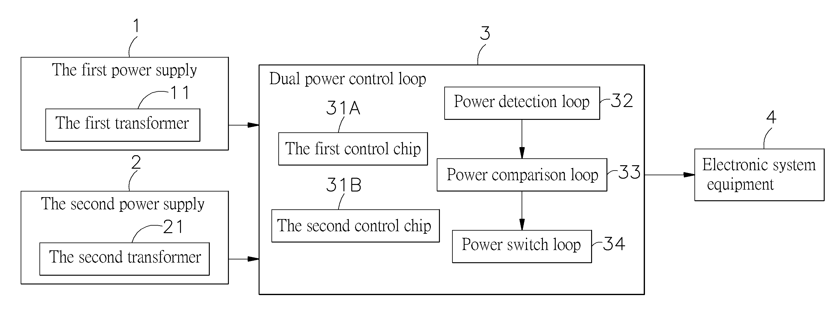
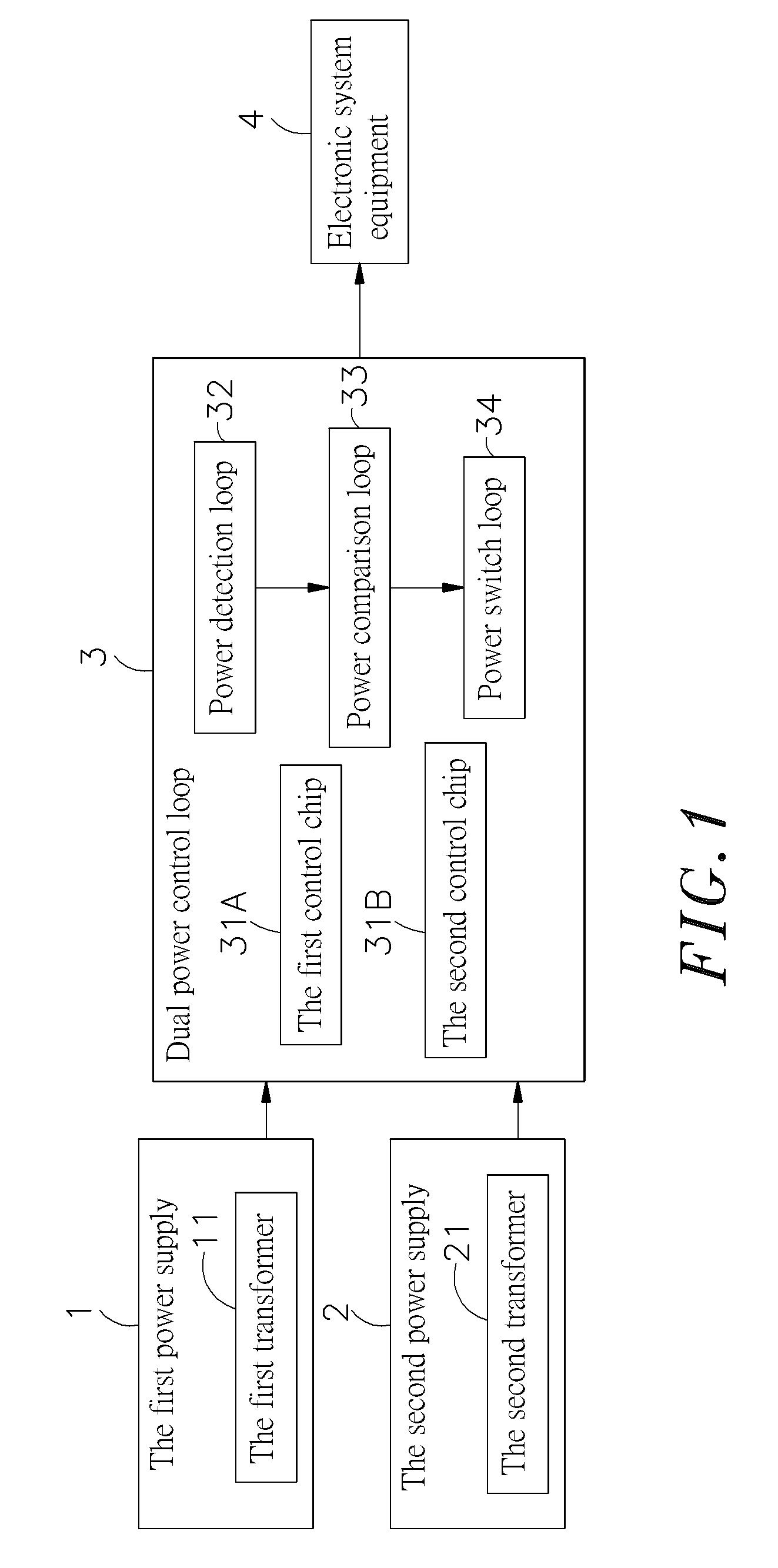
[0019]Refer to FIGS. 1 and 2, which show a circuit block diagram and a circuit diagram respectively according to one example of the preferred embodiment of the present invention. As shown clearly in these figures, the present invention comprises a first power supply 1, a second power supply 2 and a dual power control loop 3, wherein:

[0020]The first power supply 1 receives alternating current (AC) power input from utility sources, and includes a first transformer 11 that can transform AC utility power into low-voltage direct current (DC) power.

[0021]The second power supply 2 receives power input from a DC generator, and includes a second transformer 21 that ...


PUM


Abstract

The present invention relates to a low-voltage dual power loop device and method, comprising a first power supply, a second power supply and a dual power control loop, wherein the first and second power supplies provide power input to the dual power control loop, which contains the first and second control chips connected with a power detection loop, a power comparison loop and a power switch loop respectively. The first and second control chips can detect the priority of the first and second power supplies by using the power detection loop. When a power outage happens to the power supply of the first priority, it will compare the voltages by using the power comparison loop and switch over from the power supply of the first priority into the standby power supply of the second priority by using the power switch loop, so that the standby power supply continues electricity supply to external electronic equipments, avoiding losses of important data in these equipments, which may result in heavy economic losses.

Description

BACKGROUND OF THE INVENTION[0001]1. Field of the Invention[0002]The present invention relates to a low-voltage dual power loop device and method, more particularly, to a power supply system in which a dual power control loop is used to detect the priority of first and second power supplies and compare their voltages at time of power outages for switch-over from the power supply of the first priority to a standby power supply of the second priority, which continues to provide electricity.[0003]2. Description of the Prior Art[0004]As progress in electronic science and technology leads to increasing dependence on power sources, unexpected power outages will result in losses for all industries and sectors. Especially in big electronic technology companies, there are a large number of expensive electronic system equipments installed inside, and power outages will cause economic losses that are hard to estimate. For electronic system equipments (e.g. desktop PC, bare bone system, server a...

Claims


Application Information

Patent Timeline
Patent Type & Authority Applications(United States)
IPC IPC(8): H02J1/00
CPCH02J9/061H02J1/10
Inventor CHANG, KUAN-HSIUNG
Owner MOXA INC
Why Eureka
Try Eureka