Method and system for a multi-port distributed antenna

a distributed antenna and multi-port technology, applied in the field of wireless communication, can solve the problems of power inefficiency of transmitters and/or receivers in comparison to other blocks of portable communication devices

Inactive Publication Date: 2010-08-12
AVAGO TECH WIRELESS IP SINGAPORE PTE
View PDF1 Cites 140 Cited by
  • Summary
  • Abstract
  • Description
  • Claims
  • Application Information

AI Technical Summary

Benefits of technology

[0013]A system and/or method for a multi-port distributed antenna, substantially as shown in and/...

Problems solved by technology

Additionally, transmit and/or receive circuitry within such mobile wireless devices often account for a significant portion of the power consumed within these devices.
Mor...

Method used


Image

  • Method and system for a multi-port distributed antenna
  • Method and system for a multi-port distributed antenna
  • Method and system for a multi-port distributed antenna

Examples


Embodiment Construction

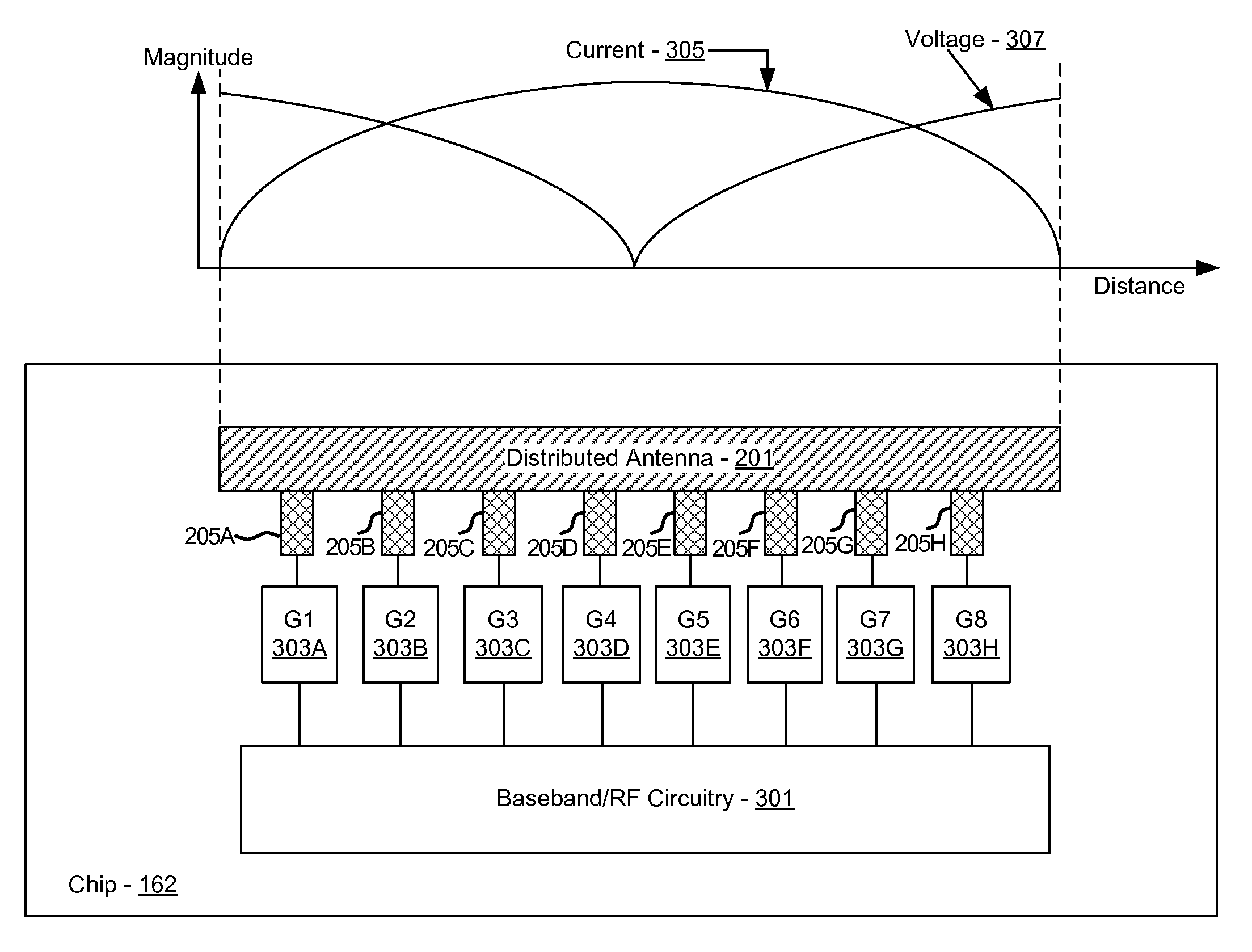
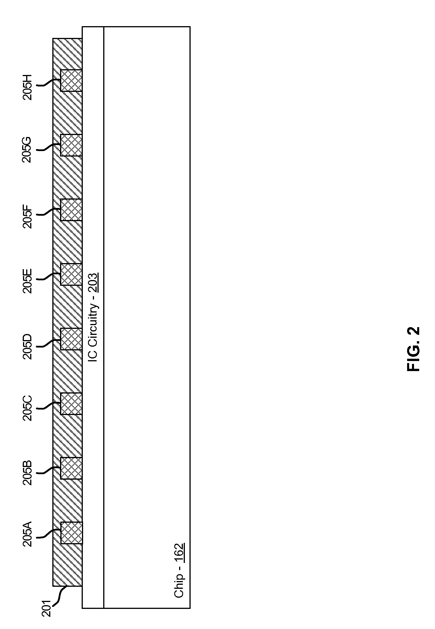
[0019]Certain aspects of the invention may be found in a method and system for a multi-port distributed antenna. Exemplary aspects of the invention may comprise configuring one or more amplifiers to communicate signals via one or more ports on a distributed antenna. A characteristic impedance of the distributed antenna at each of the one or more ports may be configured by a location of the one or more ports on the distributed antenna. The amplifiers may be impedance matched to the distributed antenna by coupling each of the amplifiers to the ports based on the characteristic impedance. The amplifiers may comprise one or more power amplifiers and / or low noise amplifiers. The signals communicated via the ports on the distributed antenna may be time division duplexed. The signals may comprise RF signals. The distributed antenna may be integrated on a chip with the amplifiers or may be located external to a chip with the amplifiers. The distributed antenna may comprise a microstrip ante...


PUM


Abstract

Methods and systems for a multi-port distributed antenna are disclosed and may include configuring one or more amplifiers to communicate signals via one or more ports on a distributed antenna. A characteristic impedance of the distributed antenna at each of the one or more ports may be configured by a location of the one or more ports on the distributed antenna. The amplifiers may be impedance matched to the distributed antenna by coupling each of the amplifiers to the ports based on the characteristic impedance. The amplifiers may include power amplifiers and/or low noise amplifiers. The signals may be time division duplexed. The signals communicated via the ports on the distributed antenna may include RF signals. The distributed antenna may be integrated on a chip with the amplifiers or may be located external to a chip with the amplifiers. The distributed antenna may include a microstrip antenna.

Description

CROSS-REFERENCE TO RELATED APPLICATIONS / INCORPORATION BY REFERENCE[0001]This application makes reference to:[0002]U.S. patent application Ser. No. ______ (Attorney Docket No. 19883US01) filed on ______;[0003]U.S. patent application Ser. No. ______ (Attorney Docket No. 19884US01) filed on ______;[0004]U.S. patent application Ser. No. ______ (Attorney Docket No. 19885US01) filed on ______; and[0005]U.S. patent application Ser. No. ______ (Attorney Docket No. 19886US01) filed on ______.[0006]Each of the above stated applications is hereby incorporated herein by reference in its entirety.FEDERALLY SPONSORED RESEARCH OR DEVELOPMENT[0007][Not Applicable]MICROFICHE / COPYRIGHT REFERENCE[0008][Not Applicable]FIELD OF THE INVENTION[0009]Certain embodiments of the invention relate to wireless communication. More specifically, certain embodiments of the invention relate to a method and system for a multi-port distributed antenna.BACKGROUND OF THE INVENTION[0010]Mobile communications have changed...

Claims


Application Information

Patent Timeline
IPC IPC(8): H04J3/00H04B1/40
CPCH04B1/18H01Q23/00
Inventor ROFOUGARAN, AHMADREZAROFOUGARAN, MARYAM
Owner AVAGO TECH WIRELESS IP SINGAPORE PTE
Why Eureka
Try Eureka