

Fiber optic cable assemblies with furcation bodies having features for manufacturing and methods of making the same
a technology of fiber optic cable and assembly, which is applied in the direction of optical elements, manufacturing tools, instruments, etc., can solve the problems of cumbersome detachment of installed furcation assemblies and reattaching them to fiber optic equipment, inability to easily integrate securing techniques into fiber optic equipment and/or not securely mount, and inability to achieve high-density fiber optic equipment design
- Summary
- Abstract
- Description
- Claims
- Application Information
AI Technical Summary
Benefits of technology
Problems solved by technology
Method used
Image

Examples
Embodiment Construction
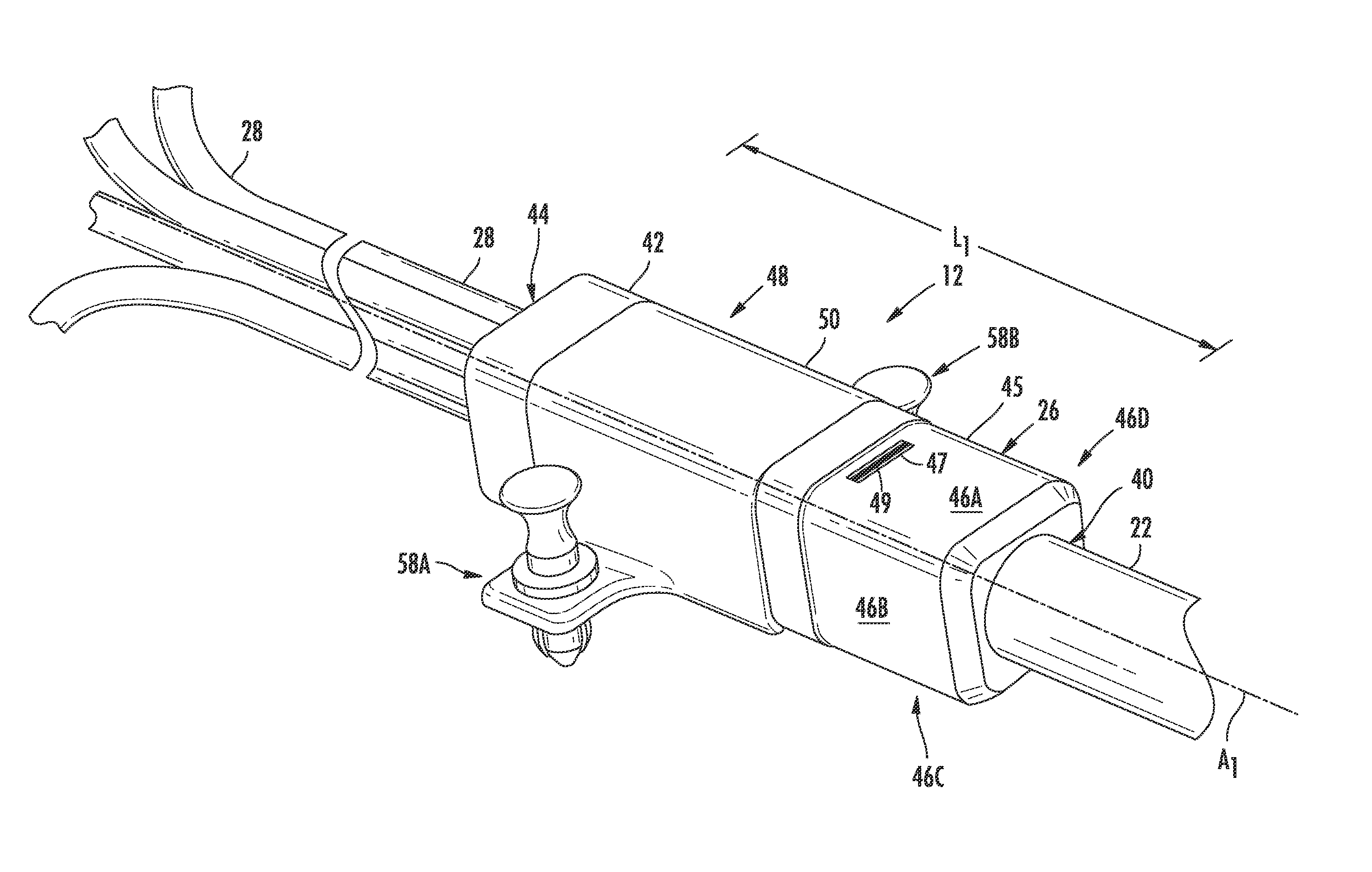
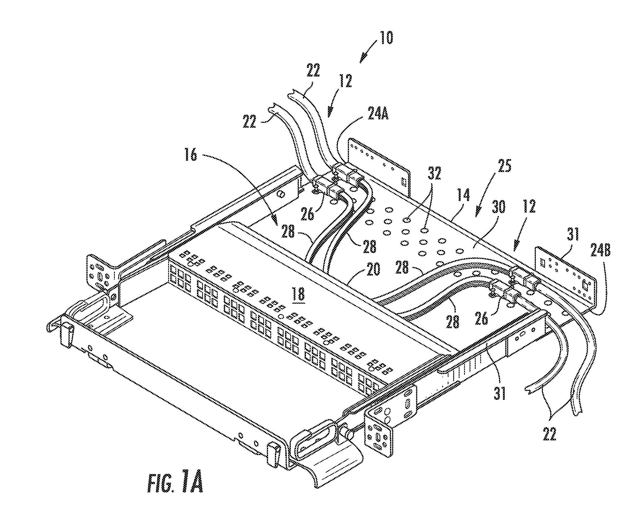
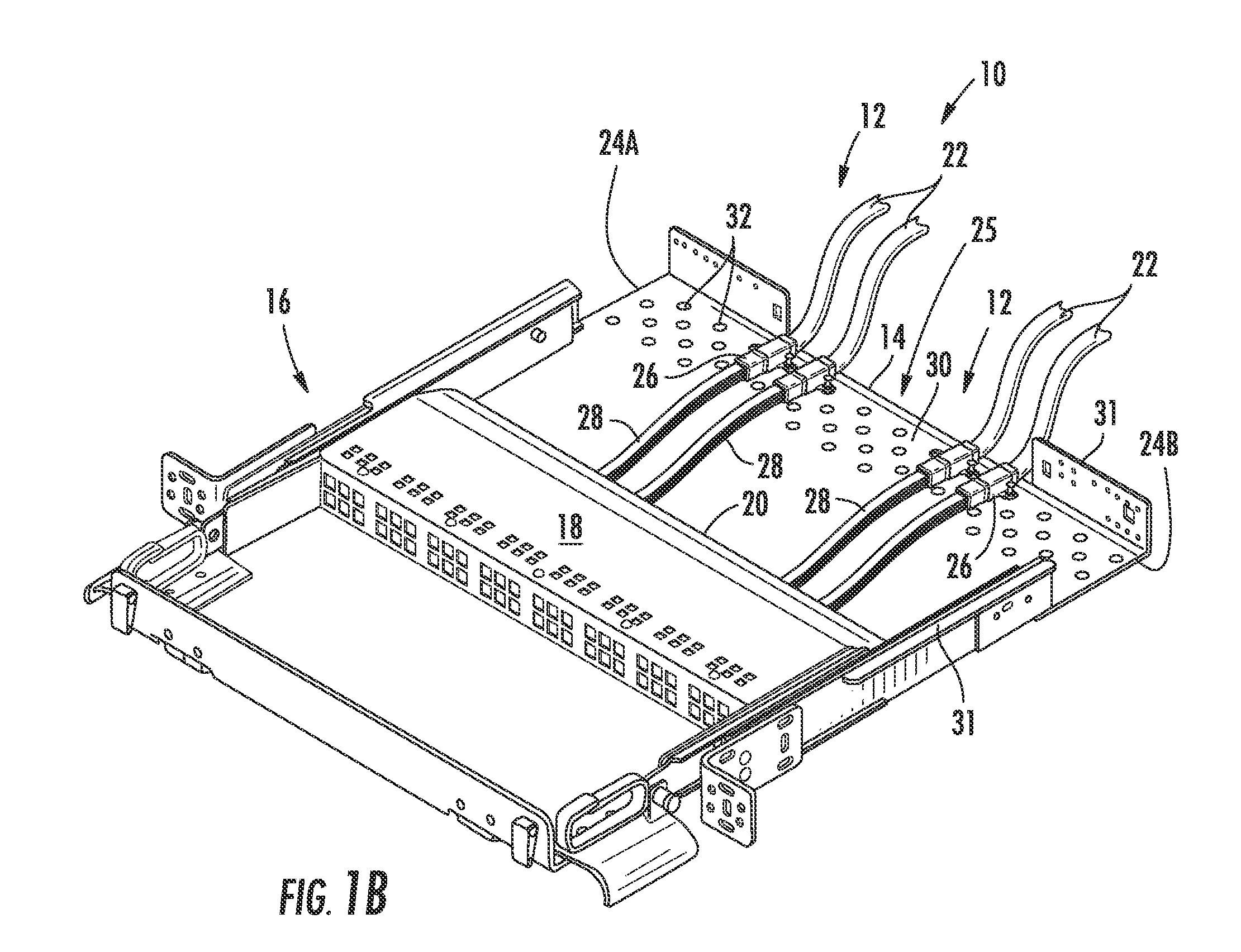
[0006]Disclosed are fiber optic cable assemblies having a fiber optic cable attached to a furcation body that includes features that are advantageous for manufacturing. The fiber optic cable is received into the furcation body and furcated into one or more furcated legs that extend from the furcation body and filled with an epoxy or adhesive. The furcated legs can have any suitable configuration such as individual buffered optical fibers, upjacket legs, ribbon, etc. Further, the furcated legs can have any suitable lengths such as staggered lengths to avoid slack storage issues and / or equal lengths. The furcation body includes an anti-rotation feature integrated therein for inhibiting rotation of the furcation body when mounted in or to fiber optic equipment and includes at least one viewing port, thereby allowing inspection during manufacturing. In other embodiments, the furcation body of the fiber optic cable assembly includes at least one weep hole for allowing air bubbles / air poc...
PUM
| Property | Measurement | Unit |
|---|---|---|
| size | aaaaa | aaaaa |
| distance L4 | aaaaa | aaaaa |
| distance L5 | aaaaa | aaaaa |
Abstract
Description
Claims
Application Information