

Machine tool
a technology of machine tools and machining units, which is applied in the field of machine tools, can solve the problems that the base frame or the machining unit cannot be easily exchanged, and achieve the effect of facilitating the separation of the machining unit and the change of the machine typ
- Summary
- Abstract
- Description
- Claims
- Application Information
AI Technical Summary
Benefits of technology
Problems solved by technology
Method used
Image

Examples
first embodiment
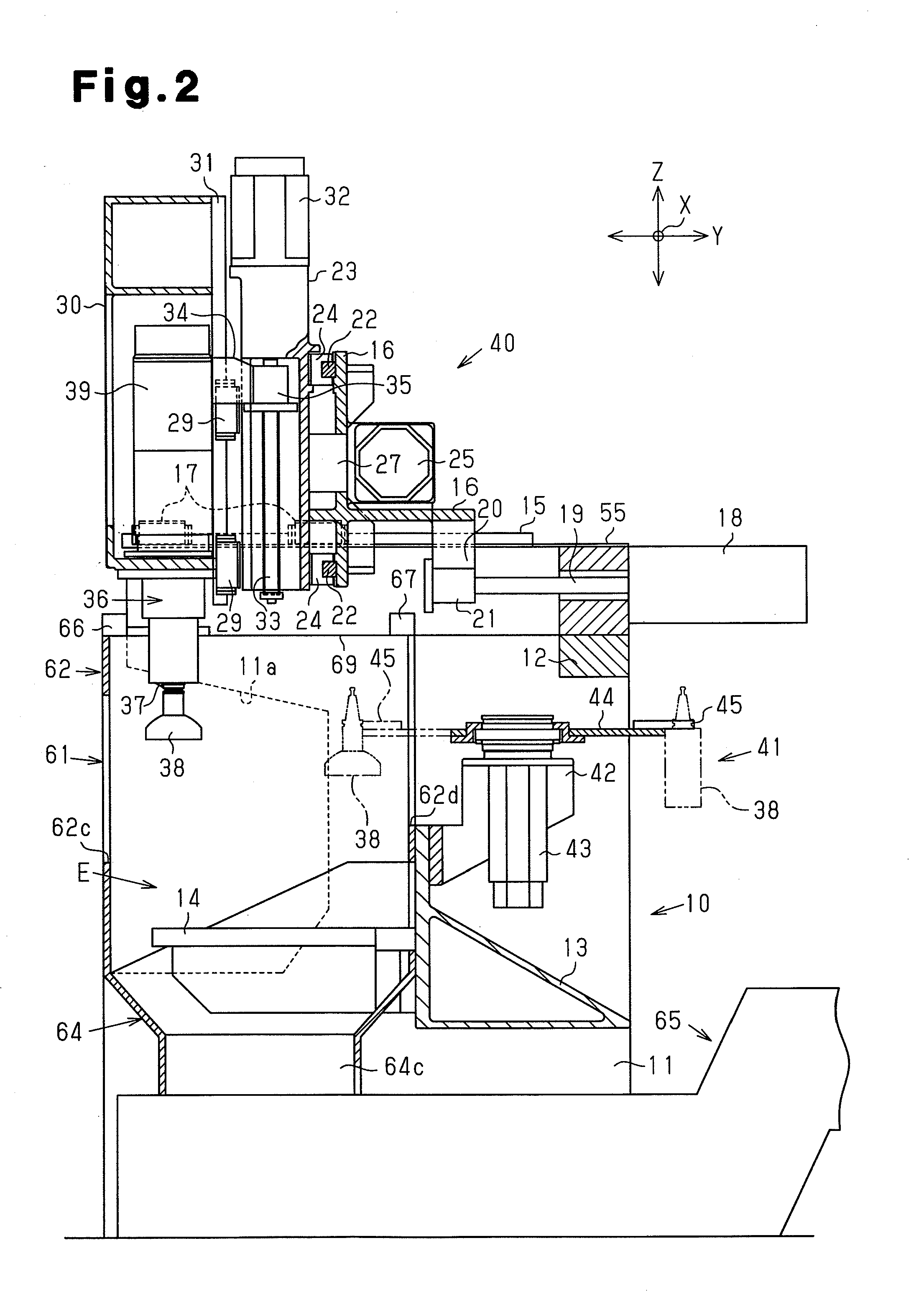
[0028]a vertical type machine tool according to the present invention will now be discussed with reference to FIGS. 1 to 6.
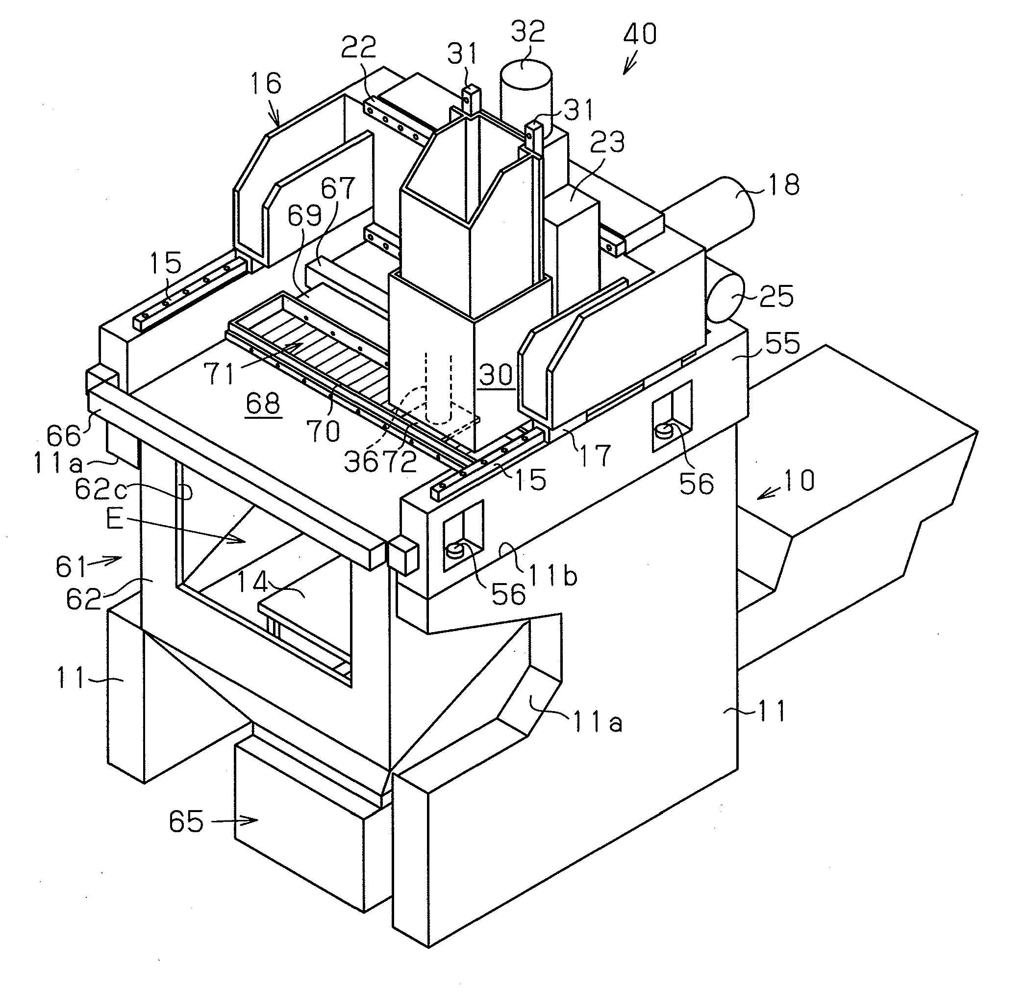
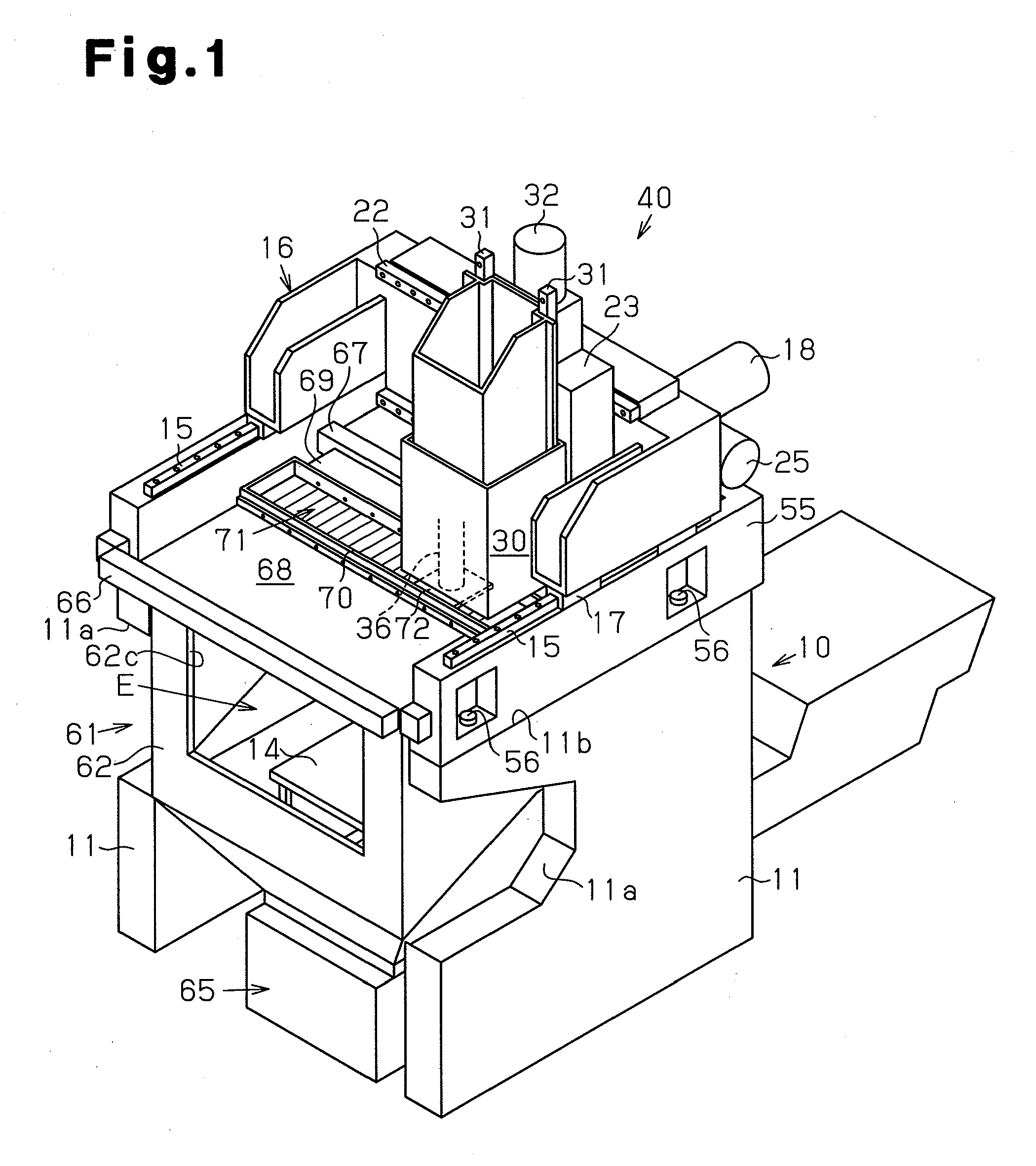
[0029]As shown in FIGS. 1 and 2, the machine tool of the first embodiment includes a base frame 10, a machining unit 40, a tool changer 41, a machining area cover 61, and a chip recovery apparatus 65. The machining unit 40 is mounted in a detachable manner on the top surface of the base frame 10. The tool changer 41 is mounted on the base frame 10. The machining area cover 61 is arranged in a machining area E defined at the inner side of the base frame 10. The chip recovery apparatus 65 is arranged under the machining area cover 61.
[0030]As shown in FIGS. 1 and 4, the base frame 10 includes two parallel left and right side frames 11, an upper connection frame 12 serving as a connection frame and integrally connecting the upper portions of the two side frames 11 so as to bridge the two side frames 11, and a lower connection frame 13 serving as a connection frame ...
second embodiment
[0051]a vertical type machine tool according to the present invention will now be discussed with reference to FIGS. 7 to 10.
[0052]In the machine tool of the second embodiment, the main cover 62 of the machining area cover 61 includes a front cover plate 73, which is formed separately from the main cover 62. The front cover plate 73 is formed to be slightly large in the leftward, rightward, and upward directions. The front cover plate 73 includes an opening defining a front window 73a for the loading and unloading of workpieces. Doors 81 and 82 open and close the front window 73a. The cover fabric accommodation case 66 and the cover fabric 68 of the top cover 63 move upward in cooperation with the opening movement of the doors 81 and 82 to form an upper open area. This facilitates the removal, attachment, and inspection of a workpiece on the workpiece table 14.
[0053]Referring to FIGS. 7 and 8, the two left and right doors 81 and 82, which open and close the front window 73a of the co...
third embodiment
[0064]a vertical type machine tool according to the present invention applied to a machining system will now be discussed with reference to FIGS. 11 and 12.
[0065]In this machining system, referring to FIG. 11, a plurality of machine tools are arranged in series along a machining line extending in the X axis direction. In the base frame 10 of each machine tool, one of left and right flanges 111a of a chute 111, which is arranged in the machining area E, is supported by a bottom surface 11f of the cutaway portion 11a in each side frame 11. A common chip recovery apparatus 65 of the machining system extends along a machining line under each machine tool. An upper plate of the main case 75 of the chip recovery apparatus 65 includes a plurality of openings 75a, each connected to the bottom of one of the chutes 111.
[0066]Each machine tool includes a robot arm type workpiece transfer apparatus 112 to sequentially load and unload workpieces for each machine tool. A machine cover 113 surroun...
PUM
| Property | Measurement | Unit |
|---|---|---|
| time | aaaaa | aaaaa |
| area | aaaaa | aaaaa |
| distance | aaaaa | aaaaa |
Abstract
Description
Claims
Application Information