Fastener for arranging a rod element on a mounting channel

Inactive Publication Date: 2010-08-12
HILTI AG
View PDF7 Cites 1 Cited by
  • Summary
  • Abstract
  • Description
  • Claims
  • Application Information

AI Technical Summary

Benefits of technology

[0010]The thread in the nut element and the thread in the opening of the engaging part both can have the same thread pitch. Since the nut element is arranged directly on the stop plate, there is no need to previously arrange said nut element on the rod element. The nut element and the engaging part are arranged on the rod element at the same time, as a result of which the effort involved in the installation and the associated time requirement are considerably reduced in comparison to prior-art approaches. Consequently, the nut element cannot be lost or forgotten. Up until now, if the preceding placement of the nut on the rod element had been forgotten, the rod element had to be dismantled or the nut had to be subsequently screwed over the free end of the rod element with great difficulty and along almost the entire longitudinal extension of the rod element. With the fastener according to the invention, it is easier to install the fastener. Users need to take along fewer individual parts for mounting the clamp fastening or suspension, and the fastener according to the invention can be produced cost-effectively.
[0019]As an alternative, the stop plate and the holding device are configured in one piece, which translates into a simple manufacture of the fastener. The holding device is made, for example, of partially punched sections of the stop plate. Advantageously, the stop plate with the holding device is manufactured by means of a punching or bending method.

Problems solved by technology

Up until now, if the preceding placement of the nut on the rod element had been forgotten, the rod element had to be dismantled or the nut had to be subsequently screwed over the free end of the rod element with great difficulty and along almost the entire longitudinal extension of the rod element.

Method used


Image

  • Fastener for arranging a rod element on a mounting channel
  • Fastener for arranging a rod element on a mounting channel
  • Fastener for arranging a rod element on a mounting channel

Examples


Embodiment Construction

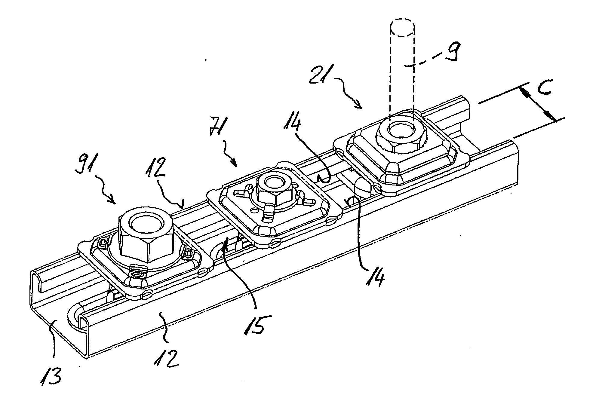
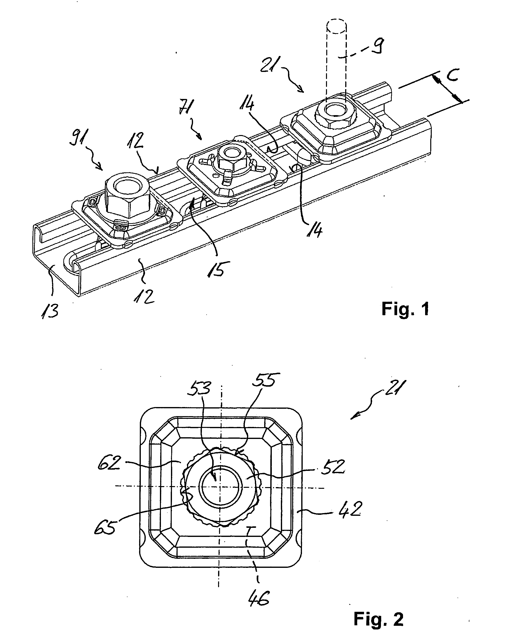
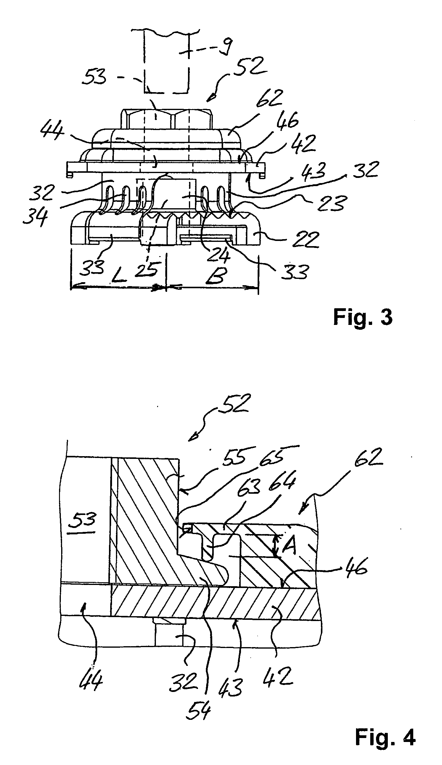
[0029]The fastener 21 shown in FIGS. 1 to 4 serves to arrange a rod element 9 such as a threaded rod, on a mounting channel 11.

[0030]The mounting channel 11 has—as the profile walls—two opposite side walls 12, a rear wall 13 that connects these side walls 12 and, opposite from this rear wall 13, an installation opening 15 that is delimited by edges 14 and that runs in the longitudinal extension of the mounting channel 11. The installation opening 15 has a clear width C that runs perpendicular to the longitudinal extension of the mounting channel 11, and this clear width C is defined by the free ends of the edges 14 that are bent towards the inside. The mounting channel 11 surrounds an interior space that is accessible from the outside through the installation opening 15.

[0031]The fastener 21 has an engaging part 22 whose width B is smaller than the clear width C of the installation opening 15 in the mounting channel 11, and whose length L is greater than the clear width C of the ins...


PUM


Abstract

The invention relates to a fastener (21) for arranging a rod element (9) on a mounting channel, said fastener (21) including an engaging part (22) that can be inserted and made to engage behind edges (14) of an installation opening of the mounting channel, whereby the engaging part (22) has an opening (25) with an internal thread for the rod element, a stop plate (42) for making contact on the outside of the mounting channel having a hole (44) through which the rod element (9) passes, and flexible connection elements (32) that connect the engaging part (22) to the stop plate (42; 76; 96) at a distance from each other. Moreover, a nut element (52) that has a hole (53) with an internal thread and that serves to secure the rod element (9) to the mounting channel can be rotatably held on the stop plate (42) using a holding device (62).

Description

[0001]This claims the benefit of German Patent Application No. DE 10 2009 000 736.9-24, filed on Feb. 10, 2009 and hereby incorporated by reference herein.[0002]The invention relates to a fastener for arranging a rod element on a mounting channel.BACKGROUND[0003]In the realm of utilities in buildings, channel systems are used to which lines, for example, for water, heating, ventilation, air-conditioning and / or electric installations can easily be attached by means of suitable fasteners such as, for instance, pipe clamps and channel nuts. Channel systems are also fitted with devices for suspending components whose rod elements can likewise be attached to the channel systems by means of suitable fasteners.[0004]A so-called C-shape mounting channel as disclosed, for example, in German utility model DE 87 15 256 U1, is often used for such a channel system. The interior space enclosed by the mounting channel is accessible from the outside through an installation opening that runs along t...

Claims


Application Information

Patent Timeline
IPC IPC(8): F16B39/28
CPCF16B37/045F16B7/187
Inventor RASS, FRANZMUGG, PETERMERHAR, THOMASWOERGARTNER, PETER
Owner HILTI AG
Why Eureka
Try Eureka