Advanced vertical shaft wind turbine power generator

a technology of wind turbines and power generators, applied in the field of vertical shaft wind turbines, can solve the problems of increasing complexity and cost of control and actuation systems, affecting the environment, and reducing the number of torsion stresses, and achieve the effect of robust structure and reducing torsion stresses

Inactive Publication Date: 2010-08-12
DALEY III JOSEPH A +1
View PDF8 Cites 4 Cited by
  • Summary
  • Abstract
  • Description
  • Claims
  • Application Information

AI Technical Summary

Benefits of technology

[0021]The configuration necessary to provide for the advanced vertical wind turbine generator design consists of a vertical wind turbine support structure which is mounted to a supporting foundation structure. On the vertical wind turbine support structure is mounted a turbine drive shaft external drive shaft bearing within which a turbine drive shaft rotates and is connected to a drive shaft coupling which connects to an external power converter. The lower disk rotates upon the vertical wind turbine support structure on lower disk rotation bearing(s) which may be located on the perimeter or underneath the lower disk. The lower disk has blade angle rotation limiters which can be a channel or protruding stop mounted to the lower disk which controls maximum / limited blade angle rotational travel. The advanced vertical wind turbine generator utilizes multiple turbine blades which incorporate uniform blade cross section geometry from top to bottom over the full length of the blade to provide a robust structure and reducing torsion stresses found in conventional wind turbine blade designs. These turbine blades are mounted to the lower disk through blade pivot bearings which are installed on the upper and lower ends of each blade. If a blade angle channel configuration is used to limit rotation, a follower pin or a follower bearing can be mounted on the bottom and or the top of the blades opposite the blade edge which supports the blade pivot bearings to self-limit freedom of rotation to allowable positions. The blades are sandwiched between the lower disk and an upper disk through the blade pivot bearings. The upper disk may or may not have blade angle rotation limiters depending on the size and loads on the structure. The turbine drive shaft may be supported above the upper disk with a vertical shaft turbine external support structure which is mounted back to the foundation structure. The resulting configuration enables the turbine blades to self adjust their angles to optimum positions through 360 degrees of disk rotation eliminating the need for external mechanical actuation required to control blade angle at a given wind direction unlike conventional vertical shaft wind turbine designs. The entire device self adjusts to shifts in wind direction eliminating the need of external mechanical actuation or wind direction monitoring devices found in conventional wind turbine designs. The resulting energy can be direct current (DC), alternating current (AC), hydraulic, pneumatic or other direct mechanical methods. Illustration shows counterclockwise rotation but geometry could be reversed to enable clockwise rotation. The invention can be made from a wide variety of materials. Vertical wind turbine power generator height, diameter, blade geometry, number of blades and blade angle variation can be tailored to particular applications.

Problems solved by technology

The current carbon based fuels used in combustion systems to generate the greatest percentage of electrical energy in the United States are considered detrimental to the environment and therefore, to human life.
Due to inefficiencies in the current art of vertical and horizontally shafted turbines the practice is to use progressively larger propeller driven generators.
These have increasingly complex and expensive controls and actuation systems which has raised technical and operational concerns.
Using progressively larger propeller systems with individual blades now reaching as long as one hundred fifty feet lengths has demonstrated high manufacturing cost, quality control issues in the manufacturing process and reliability issues due to stresses generated by high cycle and low cycle fatigue.
The current state of the design art for horizontally shafted turbines requires complex blade geometry that incorporates airfoil shapes that twist and taper from root to tip generating stresses that are difficult to minimize at continuously changing wind velocities.

Method used


Image

  • Advanced vertical shaft wind turbine power generator
  • Advanced vertical shaft wind turbine power generator
  • Advanced vertical shaft wind turbine power generator

Examples


Embodiment Construction

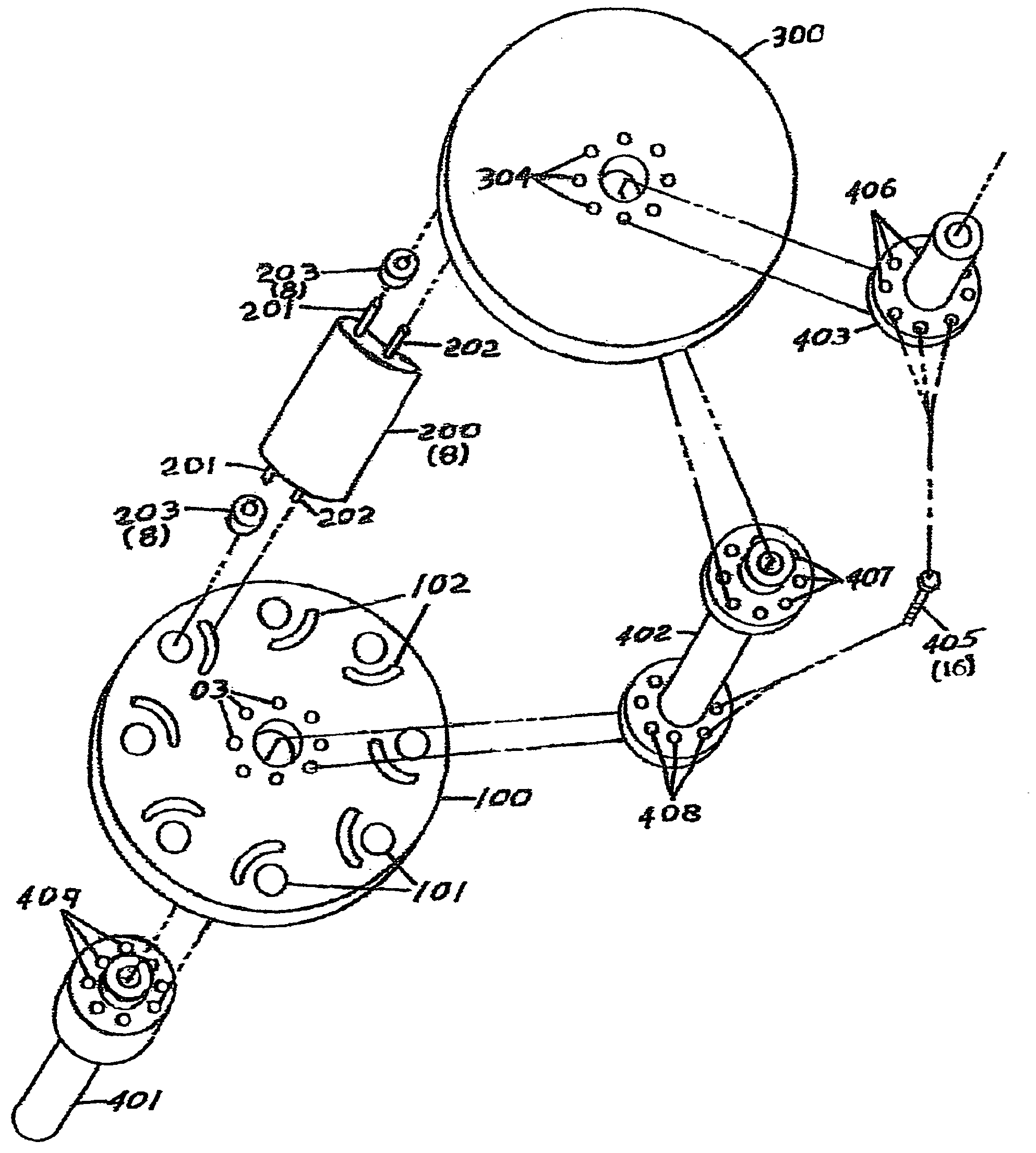
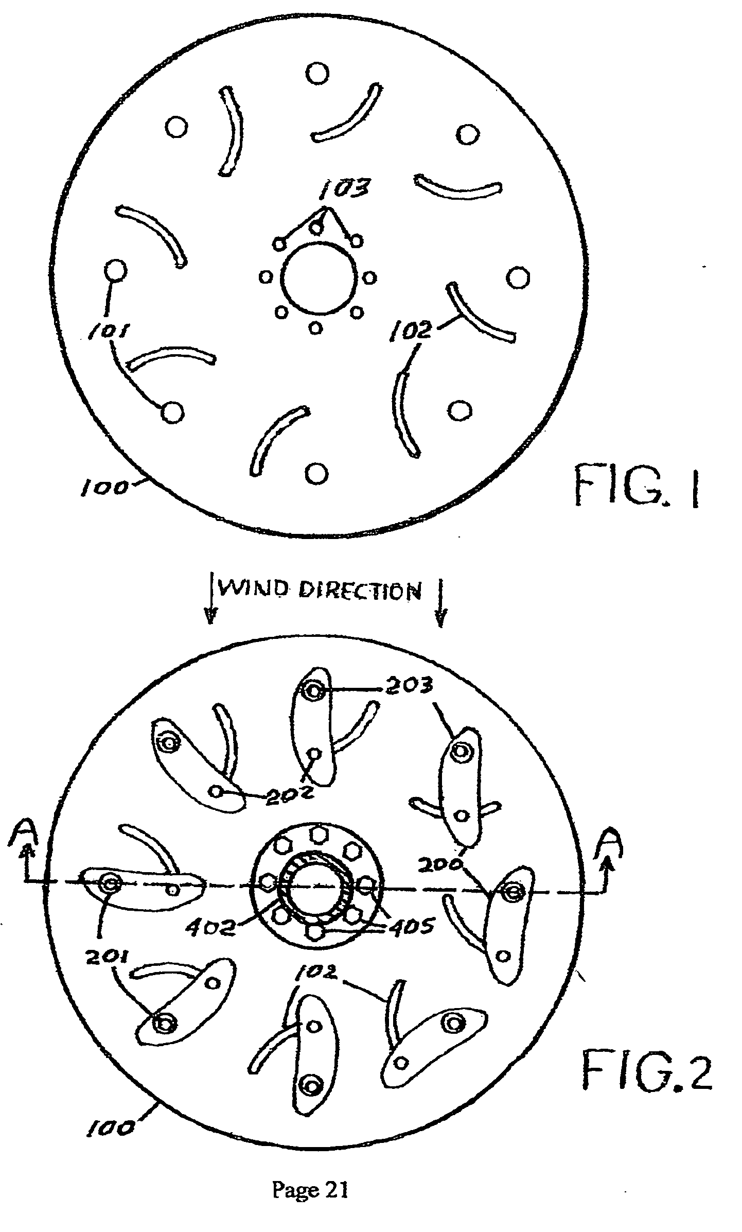
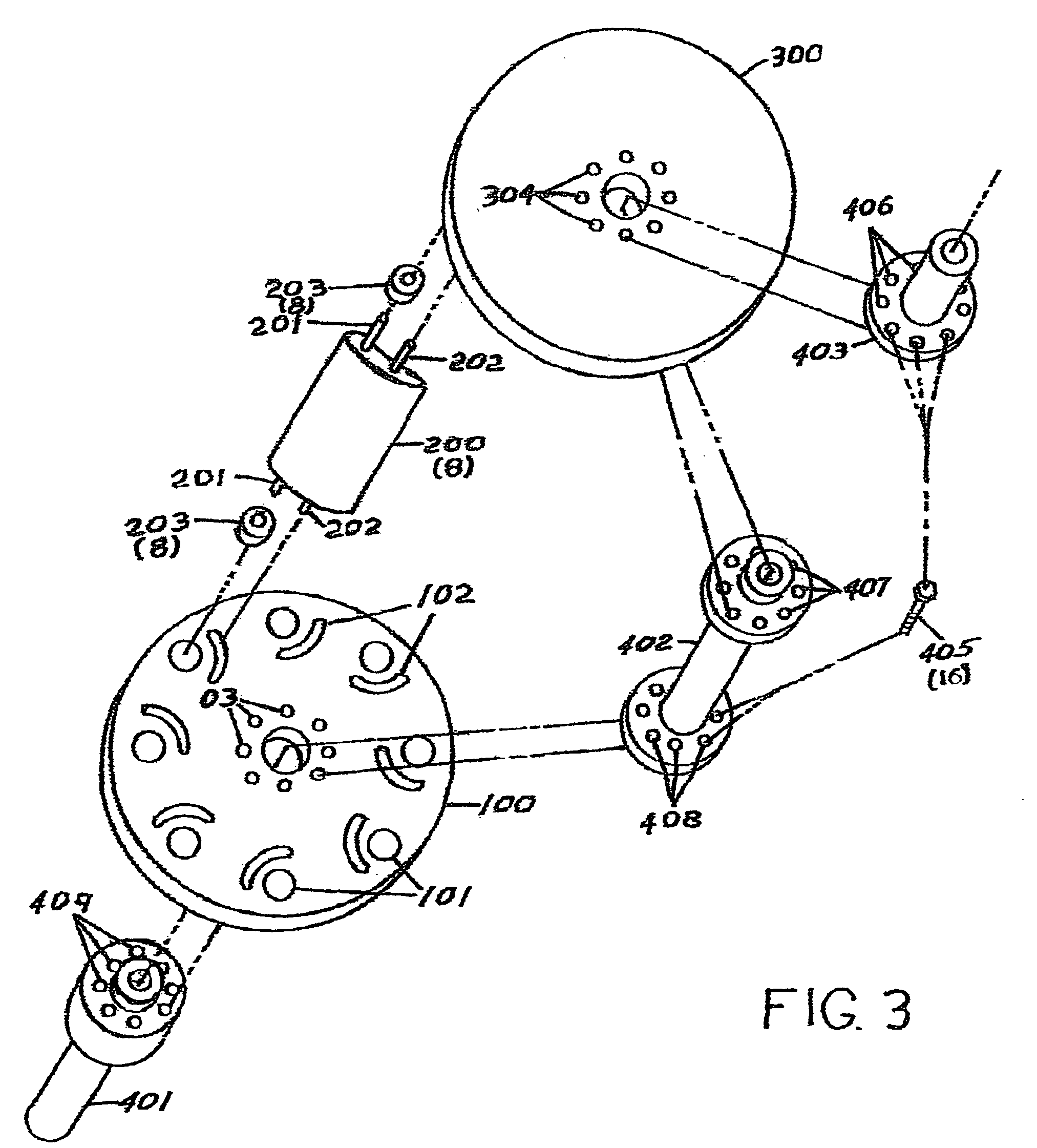
[0033]FIG. 1 The invention will now be described with reference to the drawing figures, in which the reference numerals refer to like parts throughout. The embodiment of the invention consists of a rotating assembly of aerodynamic configured blades subject to the force of the wind that will convert the rotational motion of the assembly to a force to power the driveshaft which couples to a power generator. Illustration on FIG. 1 shows the lower disk 100 configured for counter clockwise rotation, however the geometry of the disks and blade of the design could be configured in a mirror image to enable clockwise rotation. The lower disk 100 provides recesses 101 to accept the blade pivot bearings 203 identified in FIG. 2 and provides blade positioning channels 102 to accept the blade travel limiting follower pin 202 indentified in FIG. 2. Provision for assembly of the disk 100 and the lower section of the drive shaft 401 indentified in FIG. 3 and middle section of the drive shaft. 402 i...


PUM


Abstract

A design for a scalable advanced design vertical shaft wind turbine power generator which incorporates a superior symmetrical blade configuration and a unique blade mounting approach which utilizes aerodynamic forces to provide wide changes in blade positions o optimize efficiency and eliminates the need for expensive mechanical control devices while minimizing manufacturing, operational and maintenance costs.

Description

FEDERALLY SPONSORED RESEARCH[0001]Not ApplicableSEQUENCE LISTING OR PROGRAM[0002]Not ApplicableFIELD OF THE INVENTION[0003]The present invention relates generally to a vertical shaft turbine which produces wind generated power. More particularly, the present invention relates to an arrangement which captures wind determined turbine blade position to optimize output and minimize manufacturing cost and control complexity.BACKGROUND OF THE INVENTION[0004]The current carbon based fuels used in combustion systems to generate the greatest percentage of electrical energy in the United States are considered detrimental to the environment and therefore, to human life. Much effort has been directed to the direct application of sun and wind energy to replace the current fossil fuel fired electrical generation systems. Due to inefficiencies in the current art of vertical and horizontally shafted turbines the practice is to use progressively larger propeller driven generators. These have increas...

Claims


Application Information

Patent Timeline
Patent Type & Authority Applications(United States)
IPC IPC(8): F03D7/06F03D3/06
CPCY02E10/74F03D3/067Y02P70/50
Inventor DALEY, III, JOSEPH A.DALEY, JR., JOSEPH A.
Owner DALEY III JOSEPH A
Why Eureka
Try Eureka