Self-ligating orthodontic bracket

a self-ligating, orthodontic technology, applied in the field of brackets, can solve problems such as tooth decay or infection, and achieve the effect of sufficient flexibility

Inactive Publication Date: 2010-08-12
ORTHO ORGANIZERS
View PDF45 Cites 40 Cited by
  • Summary
  • Abstract
  • Description
  • Claims
  • Application Information

AI Technical Summary

Benefits of technology

[0007]Accordingly, the present invention provides for a self-ligating orthodontic bracket with a body having a bottom side including a base defined on the bottom side configured to be joined to an orthodontic band or configured to be adhered to a tooth surface, and a top side with an archwire slot. The bracket body includes a pair of spaced apart mounting arms having first and second mounting slots, and a mounting pin that forms an integral part of the latching mechanism, and that is permanently mounted in the first and second mounting slots of the mounting arms. The mounting pin is typically substantially cylindrical, but may have a varying or non-constant diameter, such as a stepped cylindrical configuration or a tapered configuration, for example. A sliding closure member is slidably mounted to the body of the bracket. The sliding closure member provides a top cover side and at least a portion of a side wall of an archwire slot, with the a top cover side and side wall side portions extending in two substantially orthogonal directions, to allow containment of the archwire from two substantially orthogonal directions, instead of only one direction, and to allow the slot width to be variable, so that the self-ligating orthodontic bracket can be either passive to active. In one presently preferred aspect, the sliding closure member is slidably movable occlusally and gingivally between a closed position covering at least a portion of the archwire slot and an open position in which the archwire slot is uncovered. In a presently preferred aspect, the sliding closure member is slidably and rotatably mounted to the body of the bracket.
[0008]The sliding closure member includes a main body portion having an interior slot that forms another integral part of the latching mechanism. The main body portion includes a middle connector portion, an upper arm extending in a first direction from the middle connector portion, an upper cover portion extending from the middle connector portion in a second direction opposing the first direction, and a lower arm extending from the middle connector portion adjacent to the upper arm. In a presently preferred aspect, the main body portion has a configuration allowing at least one of the upper and lower arms to flex with respect to the other and the middle connector portion, such that the shape of the interior slot can change as the sliding closure member is moved from one position to another, to reversibly latch the sliding closure member as desired. The upper arm and lower arm also have interior surfaces defining an interior shape of the interior slot therebetween, such that at least a portion of the slot has a width that is slightly smaller than a diameter of the mounting pin, and at least one other portion of the slot having a width larger than the diameter of the mounting pin and configured to receive the mounting pin. In one form, a slit may be formed between the upper and lower arms at the occlusal end of the upper arm and lower arms, or a slit may be formed in a desired location along the lower arm, to allow at least one of the upper and lower arms to flex with respect to the other and the middle connector portion. Alternatively, the sliding closure member may be formed without a slit, and of a material of sufficient flexibility and with at least one of the upper and lower arms being dimensioned of an appropriate thickness such that at least one the upper and lower arms can flex with respect to the other and the middle connector portion.

Problems solved by technology

However, installation and reinstallation of archwires in orthodontic brackets can be time consuming, and ligatures can become stained and may retain plaque and food debris, which can in turn result in tooth decay or infection.

Method used


Image

  • Self-ligating orthodontic bracket
  • Self-ligating orthodontic bracket
  • Self-ligating orthodontic bracket

Examples


first embodiment

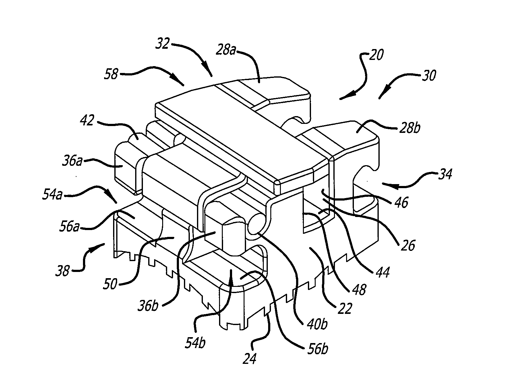
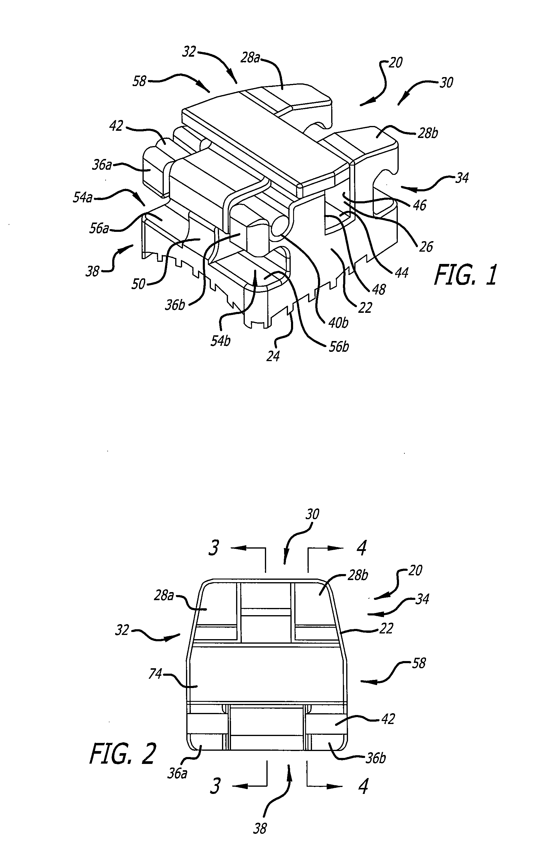
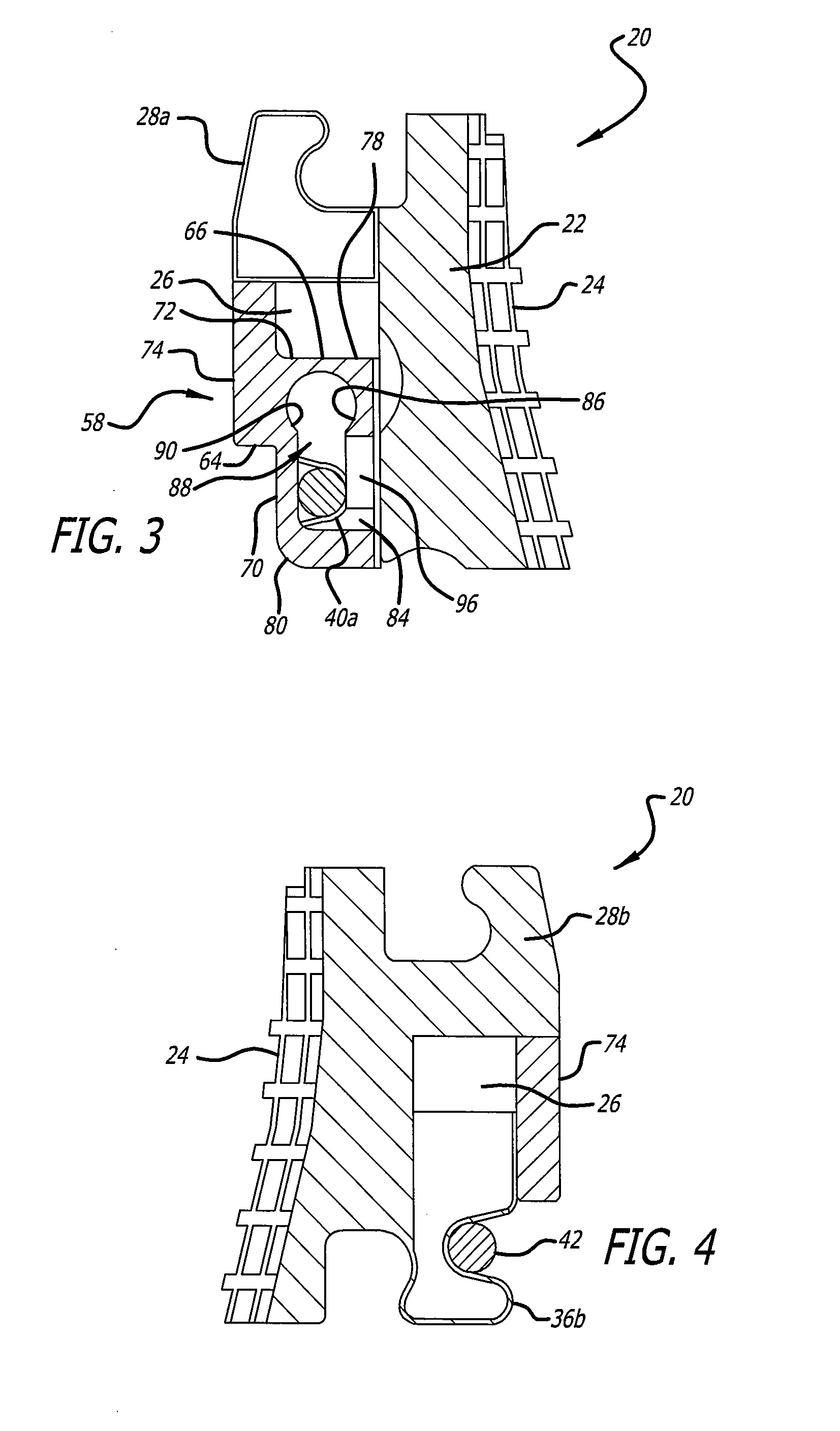
[0035]Referring to FIGS. 1-7B, in the present invention, the self-ligating orthodontic bracket 20 includes a molded unitary body 22 having a base 24 that is defined on the bottom side configured to be joined to an orthodontic band or configured to be adhered to a tooth surface (not shown). The bonding base is currently preferably formed to have a bottom rectangular grid forming a plurality of rectangular pockets. The unitary body can be formed of metal, metal alloy, ceramic, plastic, polymer, composite, or other similar materials, for example. The body also is also preferably formed to include an archwire slot 26 configured to receive an archwire (not shown). The body may also include a plurality of tiewings, such as a pair of spaced apart tiewings 28a, 28b, on the gingival 30 mesial 32 and distal 34 sides of the body.

[0036]Referring to FIGS. 1 and 5, in a presently preferred aspect, the bracket body includes pair of spaced apart mounting arms 36a, 36b, on the occlusal 38 mesial and...

second embodiment

[0041]Referring to FIGS. 8-14, in the present invention, the self-ligating orthodontic bracket is implemented in a molar buccal tube bracket 100 having a unitary body 102 including a base 104 defined on a bottom side configured to be joined to an orthodontic band or configured to be adhered to a tooth surface (not shown). This type of bracket is typically used on the molar teeth (1st molar, and 2nd molar) for straightening and alignment. The bonding base is currently preferably formed to have a bottom rectangular grid forming a plurality of rectangular pockets. The unitary body can be formed of metal, metal alloy, plastic, polymer, composite, or ceramic, for example, although other similar materials may also be suitable. The bracket body also is also preferably formed to include an archwire slot 106 that is configured to receive an archwire (not shown), for anchorage and straightening of the tooth.

[0042]The bracket body optionally may also include an auxiliary tube 108 on the gingiv...


PUM


Abstract

The self-ligating orthodontic bracket includes a bracket body with an archwire slot, a pair of spaced apart mounting arms having first and second mounting slots, and a mounting pin permanently mounted in the first and second mounting slots. A closure member is slidably mounted to the body of the bracket and movable between and reversibly latchable in at least one of a closed position in which at least a portion of the archwire slot is covered and an open position in which the archwire slot is uncovered. The closure member may also be slidably and rotatably mounted to the body of the bracket.

Description

BACKGROUND OF THE INVENTION[0001]This invention relates generally to brackets used in orthodontic treatment, and more particularly concerns self-ligating orthodontic brackets having an archwire slot, and having a latch that can slide and rotate to releasably retain an archwire in the archwire slot.[0002]Orthodontic appliances, such as brackets, buccal tubes and the like are typically applied to teeth by adhering the appliances to the surface of the teeth to orient the teeth by the application of forces on the teeth by such orthodontic appliances. Such appliances typically include an archwire slot portion for receiving an archwire and ligature elastic bands to provide corrective forces to straighten and reposition the teeth. The orthodontic appliances typically include a base portion adapted generally to conform to the shape of the teeth to which they are applied, and elastic or wire ligature ties are used to hold the archwire in the archwire slot during initial and intermediate stag...

Claims


Application Information

Patent Timeline
Patent Type & Authority Applications(United States)
IPC IPC(8): A61C7/28
CPCA61C7/287
Inventor HUFF, STEPHEN M.CRIMALDI, DOUGLAS D.COSTELLO, AARON D.
Owner ORTHO ORGANIZERS
Why Eureka
Try Eureka