Led-Based Dental Exam Lamp

a technology of led light and dental exam, which is applied in the field of operating lamps, can solve the problems of inefficient conversion process, large amount of heat, and inefficient conversion of electricity into visible light of incandescent lights, and achieve the effects of facilitating the doctor in treating the patient, reducing heat load, and efficient transfer of hea

Active Publication Date: 2010-08-12
KAVO DENTAL TECH
View PDF7 Cites 37 Cited by
  • Summary
  • Abstract
  • Description
  • Claims
  • Application Information

AI Technical Summary

Benefits of technology

[0006]The inventors have surmised that it would be desirous to provide a more energy-efficient lamp fixture capable of producing a reduced heat load, and casting illumination having a desirable color and intensity that can be adjusted to obtain desirable spectra in a single lamp. Accordingly, in one embodiment, the invention pertains to an operatory lamp used to illuminate a treatment area for treating a patient that includes structural features to efficient transfer heat from a light source and into the environment. The lamp is adapted to be movably mounted at a predetermined position above the treatment area to facilitate a doctor in treating the patient. The lamp includes a housing having a front portion toward the treatment area and a rear portion away from the treatment area. The front portion of the housing includes an elongate support member extending across a generally central axis of the housing. An LED light source is mounted on the support me...

Problems solved by technology

However, such incandescent lights suffer from an inefficient conversion of electricity to visible light.
The inefficient conversion process causes production of a considerable amount of heat, and emission of a significant amount of radiation in, or near, the infrared spectrum.
The heat generated by incandescent lighting may sometimes place an undesirable burden on environmental control systems, such as cooling systems used in dwellings.
Both the inefficient conversion process, and removing the undesired heat load from the area near the light, lead to a correspondingly larger than necessary electric utility bill.
Furthermore, in use on an operatory to illuminate an operating site on a patient, the infrared emissions may undesirably dry illuminated tissue, or may produce a feeling of discomfort in the patient.
However, fluorescent bulbs tend to be bulky, and generally produce ...

Method used


Image

  • Led-Based Dental Exam Lamp
  • Led-Based Dental Exam Lamp
  • Led-Based Dental Exam Lamp

Examples


Embodiment Construction

[0040]Although the foregoing description contains many specifics, these should not be construed as limiting the scope of the present invention, but merely as providing illustrations of some representative embodiments. Similarly, other embodiments of the invention may be devised that do not depart from the spirit or scope of the present invention. Features from different embodiments may be employed in combination.

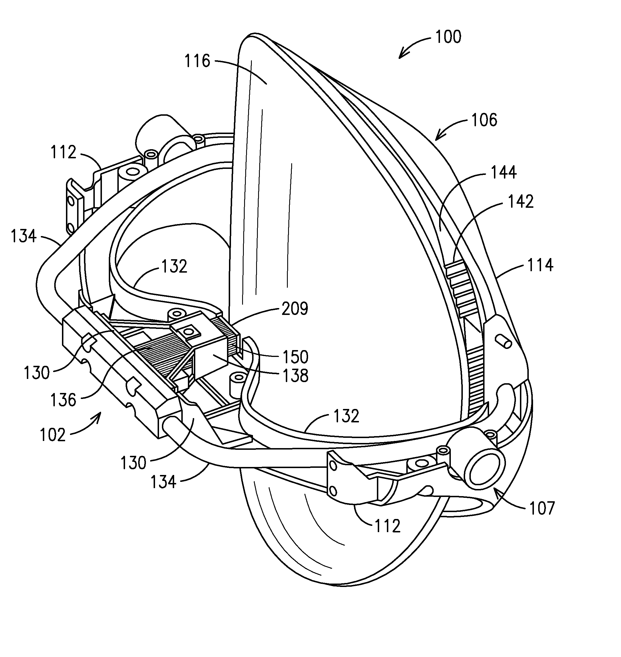
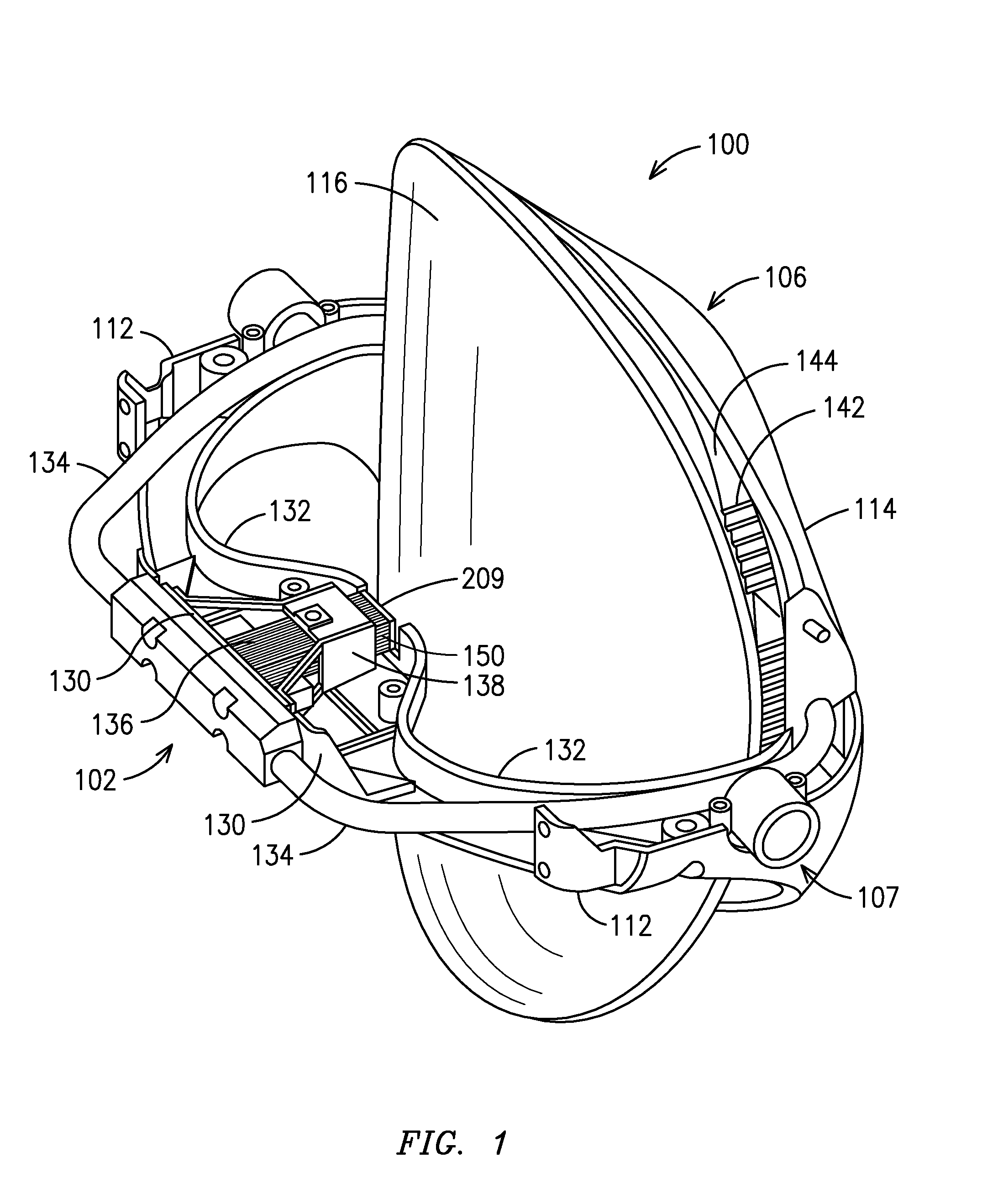
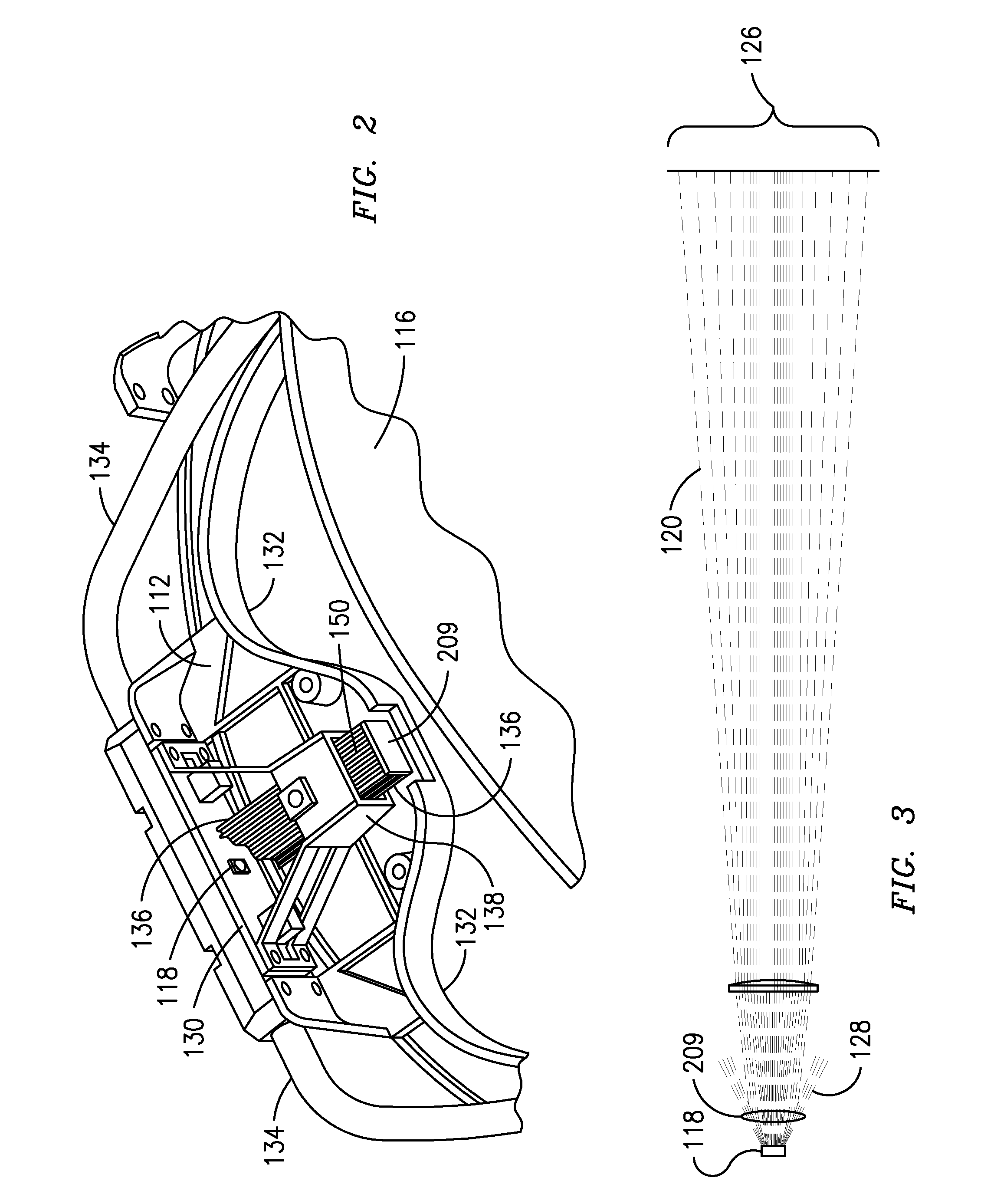
[0041]FIG. 1 illustrates a perspective view of a current embodiment of the invention, generally indicated at 100, of a light source structure constructed according to principles of the invention. Light source structure 100 may generally be characterized as a lamp. Lamp 100 is powered by electricity, and functions to provide illumination to a work area disposed a distance from the lamp front, generally indicated at 102. Desirably, the work area illuminated by lamp 100 is shadow-free, and appears relatively uniform in illumination color and intensity. For most applications, th...


PUM

PropertyMeasurementUnit
Fractionaaaaaaaaaa
Nanoscale particle sizeaaaaaaaaaa
Poweraaaaaaaaaa

Abstract

Disclosed herein is an improved dental operatory lamp having an LED light source that directs light to a reflector that in turn reflects the light to illuminate a treatment area. In one embodiment, the lamp is adapted for efficient transfer of heat from the light source and into the environment. In another embodiment, the lamp is adapted to generate a predetermined pattern of light optimal for the treatment area. In other embodiments, the lamp includes structural features that enable the lamp to maintain optimum light intensity and/or temperature. Also, disclosed herein are unique reflector embodiments that intentionally provide a generally smooth surface, without facets, that reflect light at all visible and infrared wavelengths.

Description

RELATED U.S. APPLICATION DATA[0001]This application is a continuation-in-part of application Ser. No. 12 / 287,481, filed Oct. 8, 2008, published as Pub. No. US 2009 / 0091913, which is a continuation in part of application Ser. No. 11 / 867,876, filed Oct. 5, 2007, published as Pub. No. US 2008 / 0025013 A1 on Jan. 31, 2008. Priority to these applications is claimed under 35 USC 120 and the disclosures of such are hereby incorporated herein by reference in their entirety.TECHNICAL FIELD[0002]This invention relates to an operatory lamp for illuminating a treatment area, and more particularly to a lamp that includes technological features that makes it uniquely well suited for use by a dentist or dental assistant in a dental operatory setting.BACKGROUND[0003]It has been known for an extended period of time that electricity may be harnessed to create visible light. Incandescent light emitting elements powered by electricity have been used for substantially the same period of time. However, su...

Claims


Application Information

Patent Timeline
IPC IPC(8): A61C3/00
CPCF21S48/1394F21V29/54F21V7/0008F21V7/22F21V11/10F21V14/003F21V23/04F21V23/0442F21V25/10F21V29/004F21V29/02F21V29/2212F21W2131/202F21W2131/205F21Y2101/02G02B6/0008F21V29/006F21V23/0457F21K9/50F21K9/52F21K9/00F21V29/83F21Y2113/005F21S48/328F21V29/67F21K9/60F21K9/61F21V9/00F21V14/08F21V29/74F21V29/51F21V29/56F21V29/60F21Y2113/13F21Y2115/10F21V7/26F21V7/28F21V9/20
Inventor BRIA, JOELOCKAMY, H. THOMASST. LOUIS, ROBERTHELGESEN, JOHNDAGHER, NABILVON BADINSKI, TEDBENFIELD, TOMUNSWORTH, AUSTINHEMMER, NATHAN
Owner KAVO DENTAL TECH
Why Eureka
Try Eureka