Method and Apparatus For Transmitting a Signal Within a Predetermined Spectral Mask

a predetermined spectral mask and signal technology, applied in the field of radio communication, can solve the problems of wasting ul resources, increasing traffic channels, and not getting service to new users,

Inactive Publication Date: 2010-08-12
QUALCOMM INC
View PDF1 Cites 65 Cited by
  • Summary
  • Abstract
  • Description
  • Claims
  • Application Information

AI Technical Summary

Problems solved by technology

First, more traffic channels are needed which is a capacity issue.
Second, if a network serves a data call while many new users also want voice calls, the new users will not get service unless both UL and DL resources are available.
Therefore some UL resource could be wasted.
On the one hand, there are customers waiting to make calls and no service can be made; on the other hand, the UL is available but wasted due to lack of pairing DL.
Third, there is less time for mobile stations (also known as User Equipment or UE) working in multi-timeslot mode to scan neighbor cells and monitor them, which may cause call drops and performance issues.
The demand for both types of calls continues to increase, placing increasing demands on network capacity.
This is achieved for example by dividing or adding cells and hence adding more base stations, which increases hardware costs.
This means that any additional remote station user will not be able to get service.
In reality, another capacity limit exists due to co-channel interferences (CCI) and adjacent channel interferences (ACI) introduced by high frequency re-use pattern and high capacity loading (such as 80% of timeslots and channel frequencies).
Network operators have addressed this problem in a number of ways, all of which require added resources and added cost.
Both these approaches are expensive to implement due to added network equipment.
In addition, adding cells or dividing cells into several smaller cells can result in remote stations within one cell experiencing more CCI and ACI interference from neighboring cells because the distance between cells is reduced.

Method used


Image

  • Method and Apparatus For Transmitting a Signal Within a Predetermined Spectral Mask
  • Method and Apparatus For Transmitting a Signal Within a Predetermined Spectral Mask
  • Method and Apparatus For Transmitting a Signal Within a Predetermined Spectral Mask

Examples


Embodiment Construction

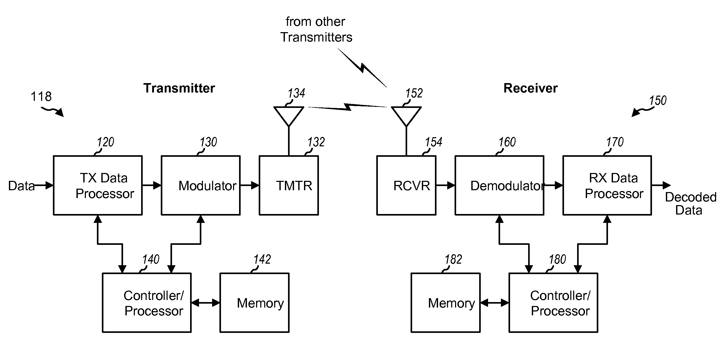
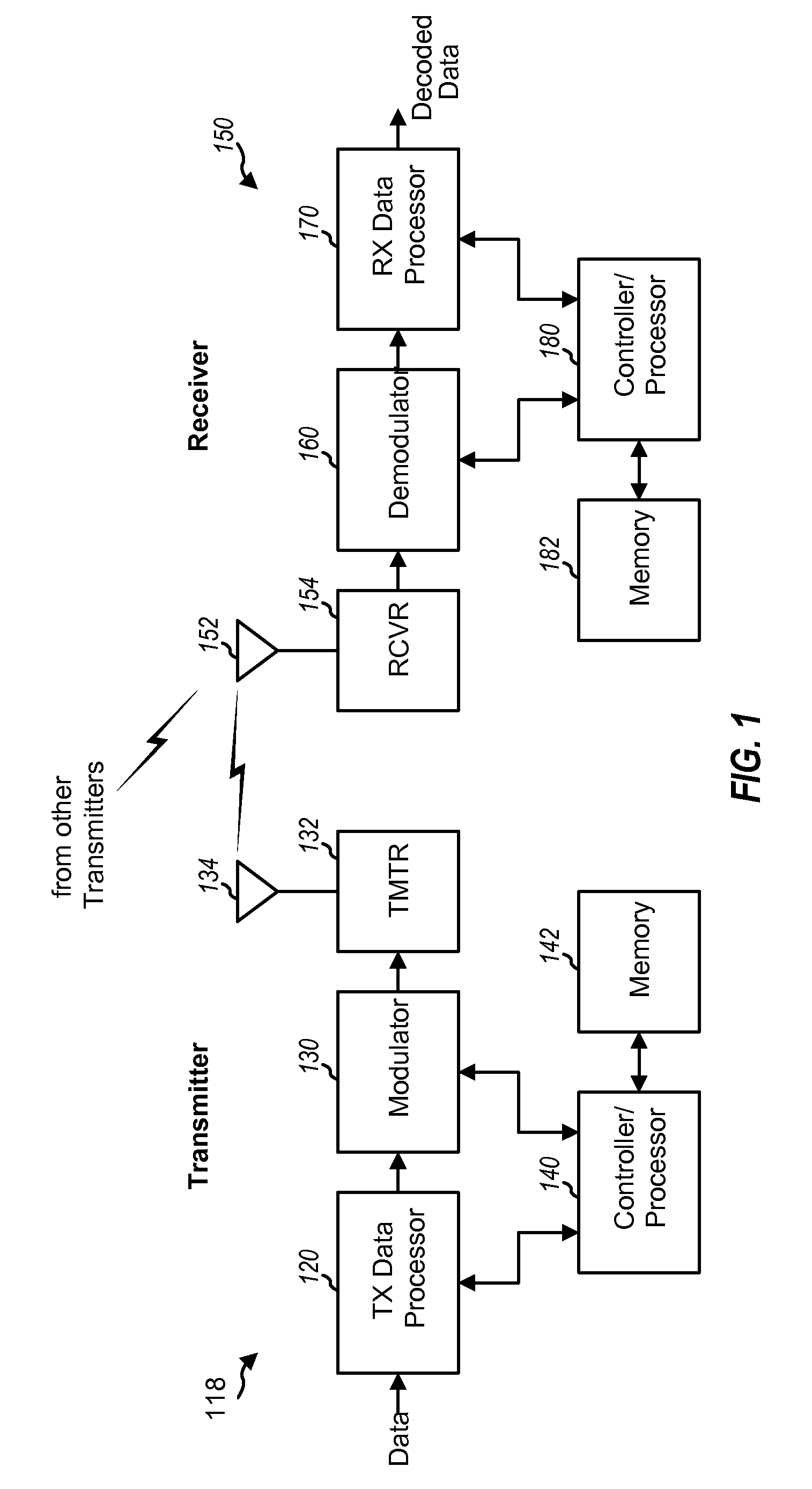
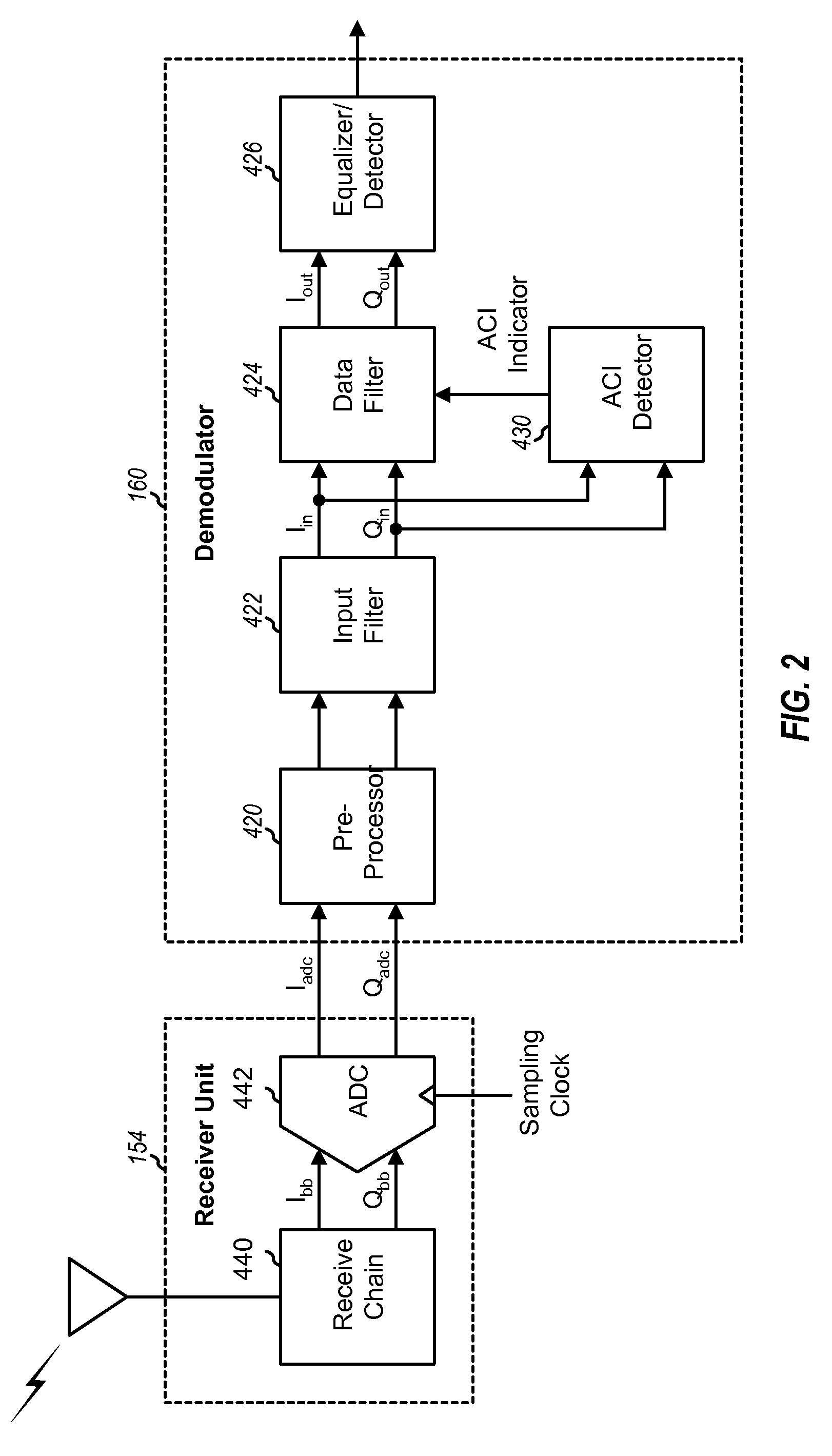
[0066]The detailed description set forth below in connection with the appended drawings is intended as a description of exemplary embodiments of the present invention and is not intended to represent the only embodiments in which the present invention can be practiced. The term “exemplary” used throughout this description means “serving as an example, instance, or illustration,” and should not necessarily be construed as preferred or advantageous over other embodiments. The detailed description includes specific details for the purpose of providing a thorough understanding of the present invention. However, it will be apparent to those skilled in the art that the present invention may be practiced without these specific details. In some instances, well known structures and devices are shown in block diagram form in order to avoid obscuring the concepts of the present invention.

[0067]Interference due to other users limits the performance of wireless networks. This interference can ta...


PUM


Abstract

The present patent application comprises a transmitting method and apparatus 240. A signal source 241 provides an input signal to a low-pass filter 242 which filters the input signal to produce a filtered signal. The filter 242 is selectively operable in a first mode in which the input signal is filtered within a narrower bandwidth; and in a second mode in which the input signal is filtered within a broader bandwidth. The filtered signal is output to a modulator 243 which modulates the filtered signal to produce a modulated signal. The modulated signal is output to a transmitter 244 which transmits the modulated signal.

Description

CLAIM OF PRIORITY UNDER 35 U.S.C. §119[0001]The present Application for Patent claims priority to Provisional Application No. 61 / 151,497, entitled “Method and Apparatus for Transmitting a Signal Within a Predetermined Spectral Mask” filed Feb. 10, 2009; Provisional Application No. 61 / 153,285, entitled “Method and Apparatus for Transmitting a Signal Withing a Predetermined Spectral Mask” filed Feb. 17, 2009; and Provisional Application No. 61 / 240,012, entitled “Method of Adapting Pulse Shape of Data Pulses For Transmission In a Digital Communications System” filed Sep. 4, 2009 and hereby expressly incorporated by reference herein.FIELD OF THE INVENTION[0002]The invention relates generally to the field of radio communications and in particular to the increasing of channel capacity in a radio communications system.BACKGROUND[0003]More and more people are using mobile communication devices, such as, for example, mobile phones, not only for voice but also for data communications. In the ...

Claims


Application Information

Patent Timeline
Patent Type & Authority Applications(United States)
IPC IPC(8): H04B1/04
CPCH04L27/20H04L25/03834
Inventor YU, ZHI-ZHONGDHANDA, MUNGAL S.
Owner QUALCOMM INC
Why Eureka
Try Eureka