
Nebulizer having flow meter function

a flow meter and nebulizer technology, applied in the field of nebulizers, can solve the problems of difficulty in reproducing the dose, difficulty in estimating the dose of the drug being given, and large particle size to reach the bottom of the lungs, so as to improve the penetration of nebulized medicine into the airway.

Active Publication Date: 2010-08-12
PNEUMOFLEX SYST
View PDF17 Cites 62 Cited by
  • Summary
  • Abstract
  • Description
  • Claims
  • Application Information

AI Technical Summary

Benefits of technology

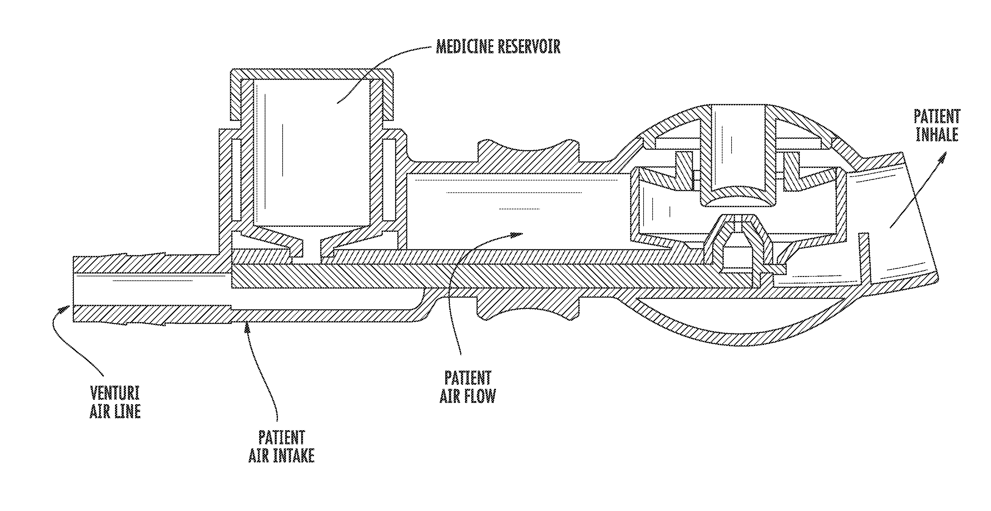
[0017]In yet another example, the mixing chamber is configured as a rainfall chamber and a diffuser is positioned within the rainfall chamber upon which the medicine that is nebulized impacts and configured to break up droplets of medicine expelled from the venturi into smaller sizes. In yet another example, a plurality of medicine receivers are on the main body, each shaped to match a shape uniquely associated with a different medicine receiver. The air channel section is configured to receive medicine from a medicine container that is received within the medicine receiver. Air curtain conduits are configured in another example to apply a curtain of air above and below the nebulized medicine and air to enhance penetration of nebulized medicine into the airway of the patient. The air sensor in an example is configured to measure air velocity, and in another example, is configured to measure air pressure.

Problems solved by technology

Further, the particle size is often too large to reach the bottom of the lungs where the medication may be most needed.
There is difficulty in estimating the dose of the drug being given to a patient and there is difficulty in reproducing that dose.
There is a possibility of contamination when opening the initially sterile kit, poring medication into the cup, and assembling the pieces for use by a patient.
There is also considerable inefficiency in the medication delivery, with much of it being deposited in the throat, rather than in the lungs.

Method used


Image

  • Nebulizer having flow meter function
  • Nebulizer having flow meter function
  • Nebulizer having flow meter function

Examples


Embodiment Construction

[0046]The present invention will now be described more fully hereinafter with reference to the accompanying drawings, in which preferred embodiments of the invention are shown. This invention may, however, be embodied in many different forms and should not be construed as limited to the embodiments set forth herein. Rather, these embodiments are provided so that this disclosure will be thorough and complete, and will fully convey the scope of the invention to those skilled in the art. Like numbers refer to like elements throughout.

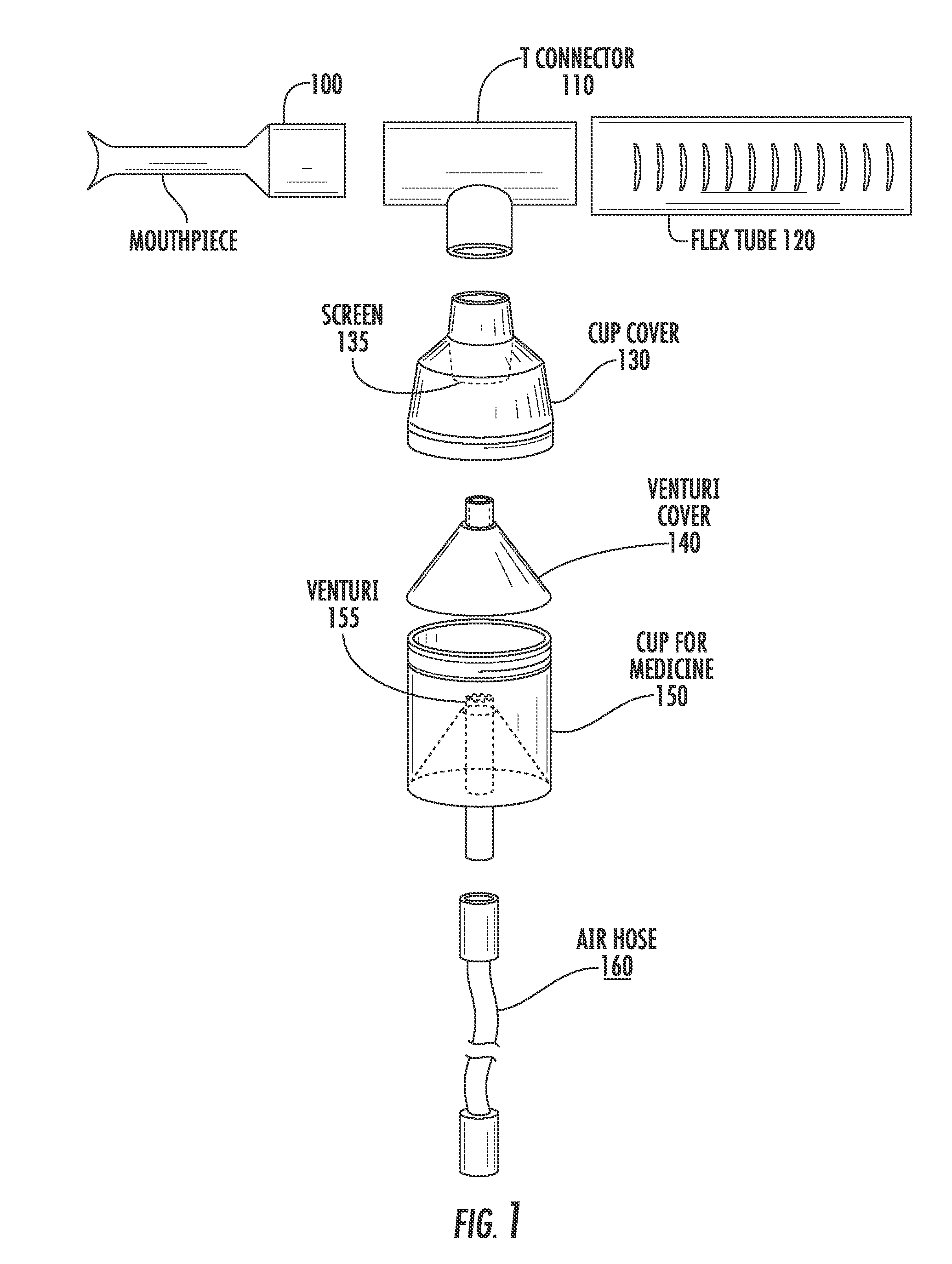
[0047]The description relative to FIGS. 2-19 set forth much of the description in the above-identified and incorporated by reference '993 and '689 patent applications.

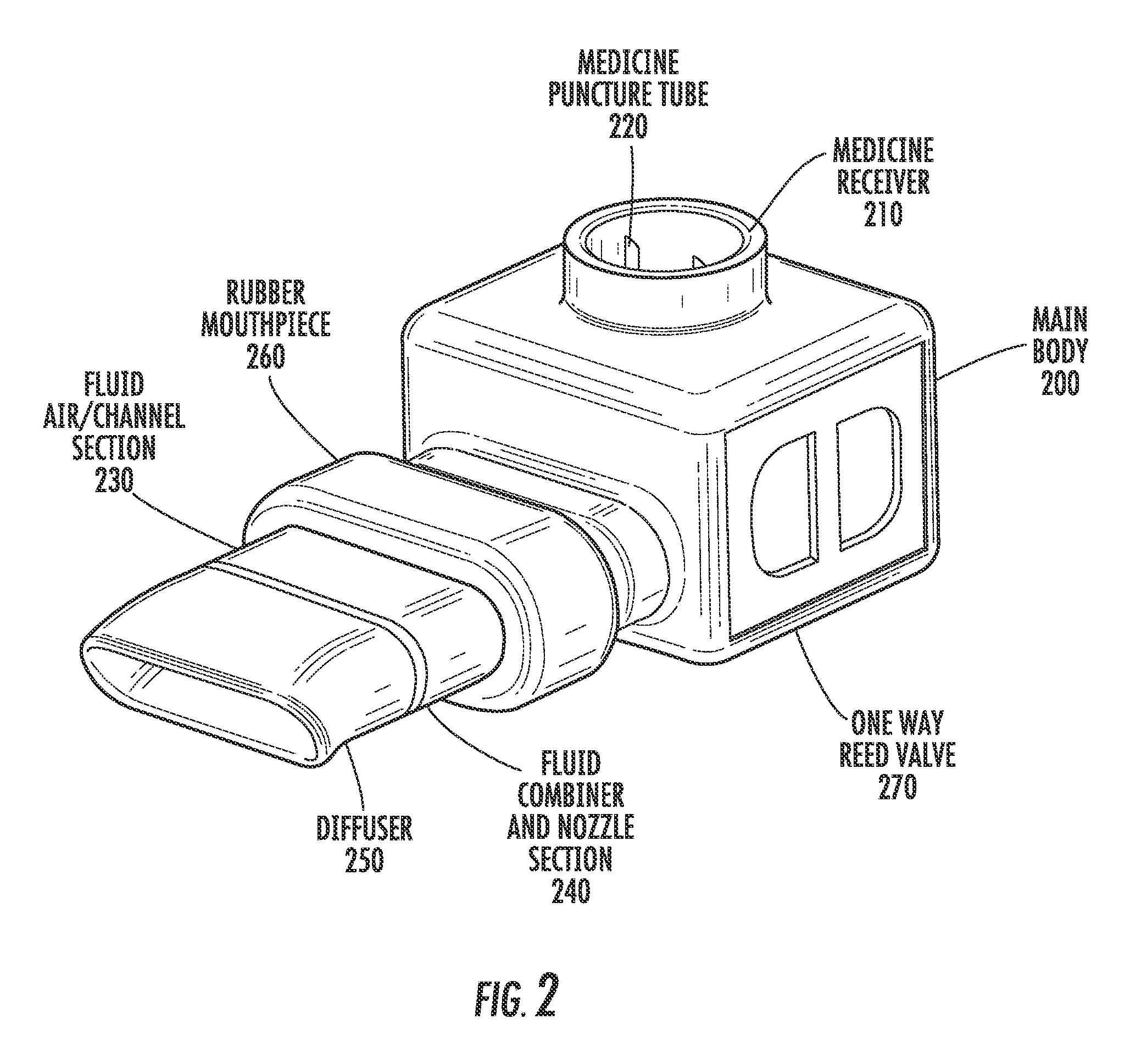
[0048]FIG. 2 is a perspective view of an improved nebulizer in accordance with one aspect of the invention. The nebulizer comprises a main body 200 which has a medicine receiver 210. Extending from the main body is a fluid air channel section 230. The fluid combiner and nozzle section 240 the...


PUM


Abstract

In accordance with non-limiting examples, a nebulizer includes a main body comprising an air channel section and further comprising a mixing chamber and a venturi positioned to be placed within the patient's oral cavity and configured to receive medicine and air and mix the medicine and air within the mixing chamber and receive the air flow through the venturi and cause the medicine entering the mixing chamber to be atomized by the action of air flowing through the venturi. An air flow sensor is associated with the main body and configured to measure the air flow created by the patient's one of at least inhaling and exhaling air.

Description

RELATED APPLICATION(S)[0001]This application claims priority to U.S. provisional application Ser. No. 61 / 160,735, filed Mar. 17, 2009, and is a continuation-in-part of application Ser. No. 11 / 557,993, filed Nov. 9, 2006, which is a continuation-in-part of application Ser. No. 11 / 431,689, filed May 10, 2006, which is a continuation-in-part of application Ser. No. 10 / 783,442, filed Feb. 20, 2004, and each of these applications is hereby incorporated by reference into this specification in their entirety.FIELD OF THE INVENTION[0002]The present invention relates to the field of nebulizers, and more particularly, this invention relates to intra-oral nebulizers.BACKGROUND OF THE INVENTION[0003]Inhalation is a very old method of drug delivery. In the twentieth century it became a mainstay of respiratory care and was known as aerosol therapy. Use of inhaled epinephrine for relief of asthma was reported as early as 1929, in England. Dry powder inhalers have been utilized to administer penici...

Claims


Application Information

Patent Timeline
IPC IPC(8): A61B5/087A61M11/00
CPCA61M11/02A61M15/002A61M2016/0021A61M2016/0036A61M2202/0468A61M2205/3553A61M2205/3569A61M2205/3584A61M2205/3592A61M2205/502A61M2205/52A61M2205/6045A61M2205/8225A61M2206/18A61M15/0065A61M15/009A61M15/06A61M16/20A61M15/0003A61M11/06
Inventor ADDINGTON, W. ROBERTMILLER, STUART P.PHELIPA, MICHAEL M.STEPHENS, ROBERT E.
Owner PNEUMOFLEX SYST
Learn More