
Method for operating a surgical power tool

a surgical power tool and power tool technology, applied in the direction of manufacturing tools, coupling device connections, applications, etc., can solve the problems of reducing the operability of surgical power tools, affecting the operability of sterilization medium into mechanical actuation assemblies, and sometimes disadvantageous mechanical actuation assemblies for surgical power tools. , to achieve the effect of avoiding or reducing damage to components

Active Publication Date: 2010-08-12
STRYKER EURO OPERATIONS HLDG LLC
View PDF32 Cites 8 Cited by
  • Summary
  • Abstract
  • Description
  • Claims
  • Application Information

AI Technical Summary

Benefits of technology

[0019]The switch may comprise two or more contacts. In the case of a switch having at least two contacts, the first contact and the second contact may be kept spaced apart from one another by a spring force. In this way, the effect which can be achieved is that the second switching state is assumed only when the actuation force is sufficient to overcome the spring force.
[0021]The actuation assembly may further comprise an elastic cover which provides a bearing surface (e.g. for a finger) for the application of the actuation force. The elastic cover may have sealing functions in the region of the actuation assembly or between the actuation assembly and a tool housing which houses the actuation assembly. In this way, the ingress of sterilization media into the actuation assembly and / or into the tool housing can be avoided. The elastic cover may further exhibit damping properties in order to avoid or at least reduce damage to components of the actuation assembly due to impacts or shocks in the surgical environment. For this purpose, the cover may have an increased material thickness at least in regions.

Problems solved by technology

However, mechanical actuation assemblies are sometimes disadvantageous for surgical power tools, if the tools have to be sterilized at any rate.
This is due to the fact that the moving components of such assemblies are very difficult to seal against the ingress of liquid or gaseous sterilization media.
The penetration of a sterilization medium into mechanical actuation assemblies is detrimental to their operability.

Method used


Image

  • Method for operating a surgical power tool
  • Method for operating a surgical power tool
  • Method for operating a surgical power tool

Examples


Embodiment Construction

[0037]Exemplary embodiments of surgical power tools, of an actuation assembly provided therefor, and of an operating method suitable therefor are explained below. Corresponding elements are provided with corresponding reference symbols.

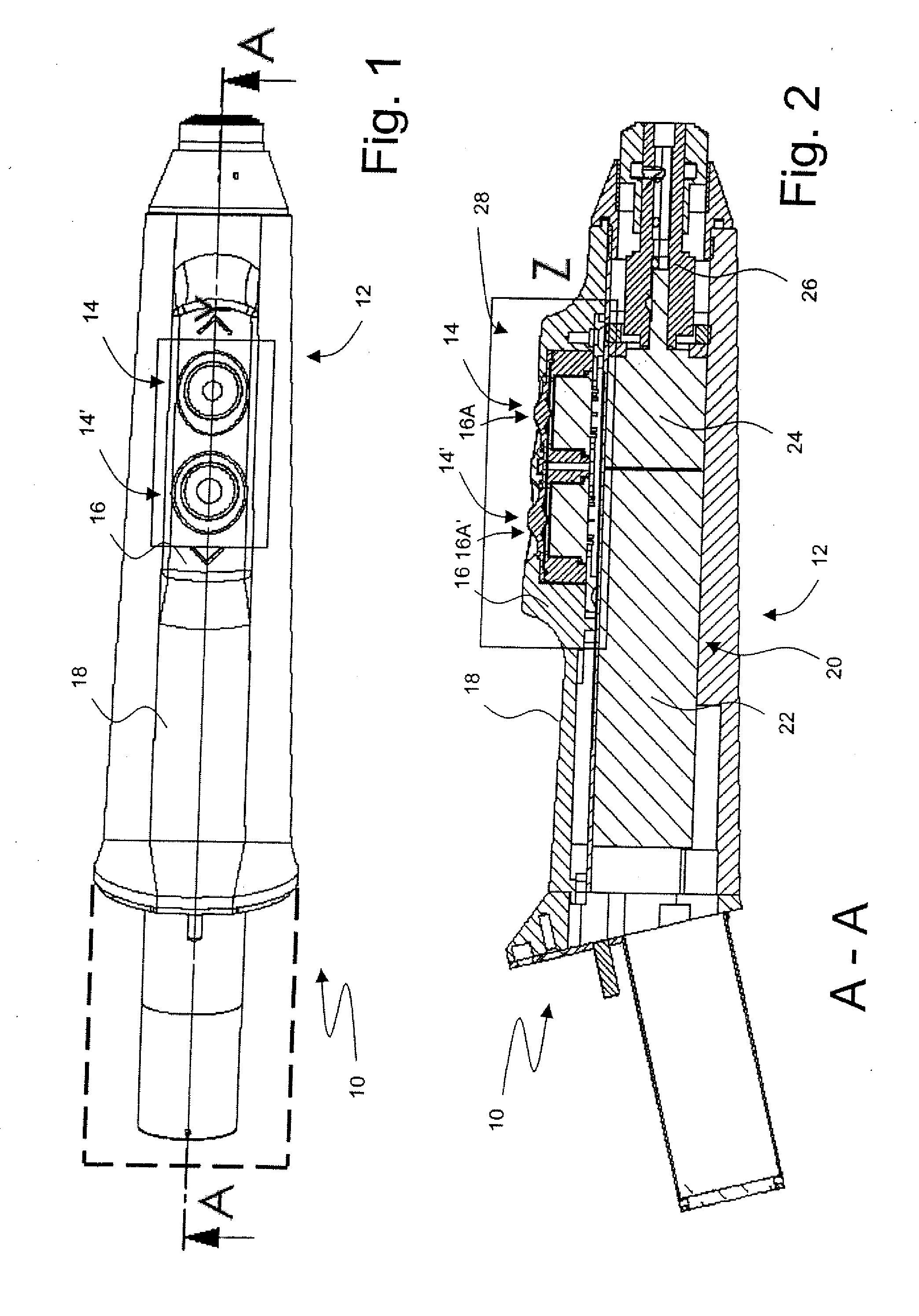
[0038]FIG. 1 shows a plan view of a surgical power tool 10 in the form of a battery-operated screwdriver. The surgical power tool 10 has an elongated, approximately cylindrical housing 12 made of aluminium, onto the rear side of which a battery pack (shown only schematically and in broken lines) can be plugged removably.

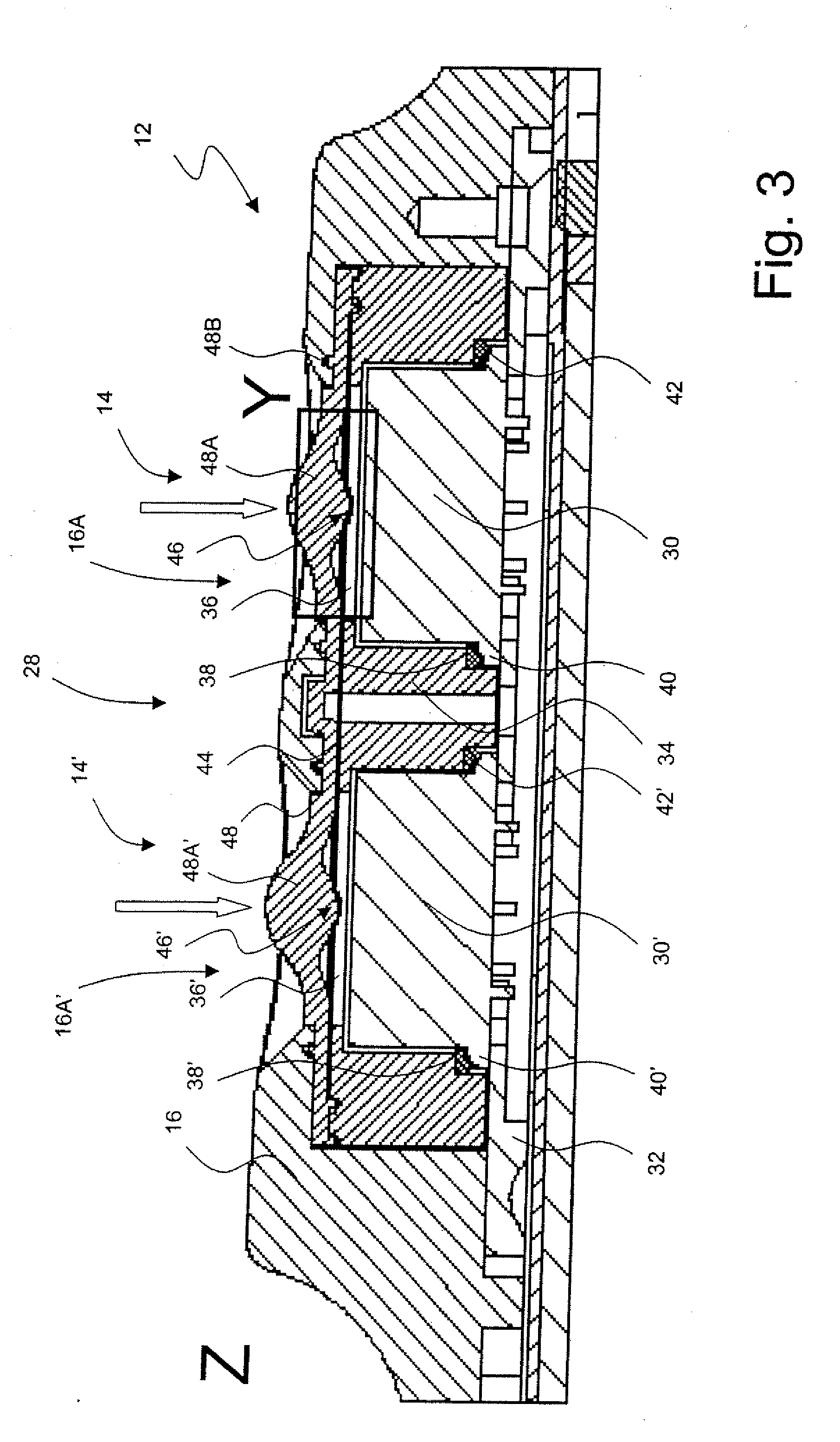
[0039]In the exemplary embodiment, the surgical power tool 10 comprises two actuation assemblies 14, 14′ for controlling different tool functions. The actuation assemblies 14, 14′ are provided in a front region of the housing 12 which is remote from the battery pack. As can be seen in particular from the sectional view illustrated in FIG. 2 along the line A-A of FIG. 1, the actuation assemblies 14, 14′ are received in a collar 16 of th...


PUM


Abstract

A surgical power tool has an actuation assembly which comprises a force sensor and a switch. The force sensor is provided to determine an actuation force produced by the user, and the switch is transferred by the actuation force from a first switching state to a second switching state. A combined evaluation of the force sensor signal and of the switching state enables, for example, a plausibility check for increasing the operational reliability of the power tool.

Description

BACKGROUND OF THE INVENTION[0001]The invention relates generally to surgical power tools such as electric-motor-driven drills, bone saws and screwdrivers. To be more precise, the invention relates to a surgical power tool comprising an actuation assembly having a force sensor.[0002]For several decades a wide variety of power tools have been used by surgeons in their work. Conventional surgical power tools frequently comprise mechanical actuation assemblies having slide switches, tumbler switches or rotary knobs for controlling certain functionalities of the tools. However, mechanical actuation assemblies are sometimes disadvantageous for surgical power tools, if the tools have to be sterilized at any rate. This is due to the fact that the moving components of such assemblies are very difficult to seal against the ingress of liquid or gaseous sterilization media.[0003]The penetration of a sterilization medium into mechanical actuation assemblies is detrimental to their operability. F...

Claims


Application Information

Patent Timeline
Patent Type & Authority Applications(United States)
IPC IPC(8): A61B19/00B23Q5/04
CPCA61B17/1622A61B17/1626A61B2017/00017A61B2019/4868H01H9/06H01H2300/014H01H2225/002H01H2225/018H01H2225/03H01H2239/052H01H2223/003A61B2090/0813
Inventor IPPISCH, ANDREAS
Owner STRYKER EURO OPERATIONS HLDG LLC
Learn More