Data modulating device and method thereof

a data modulator and data technology, applied in the field of data modulator and method, can solve the problems of increasing the number of data identification errors, difficult to set the threshold for “threshold check” and the amplitude of the read signal within the pag

Inactive Publication Date: 2010-08-12
SONY CORP
View PDF1 Cites 58 Cited by
  • Summary
  • Abstract
  • Description
  • Claims
  • Application Information

AI Technical Summary

Benefits of technology

[0089]According to the above configuration, the values are inverted of decoding results along with one-time amplitude rank order switching may be arranged to become 1. Thus, as described above, in the case of using a technique for providing the LLR according to whether or not there is an inverted bit value serving as a decoding result along with amplitude rank order switching, computation of an LLR may be arranged to be suitably executed. That is to say, in this result, LDPC (Low Density Parity Check) decoding performance may be arranged to further improve.

Problems solved by technology

However, with the hologram recording / reproducing system, change in the amplitude of a read signal within a page is relatively great, and setting of a threshold for “threshold check” is very difficult.
That is to say, from this point of view, using threshold check with the hologram recording / reproducing system causes increase in data identification errors, and it is very difficult to execute suitable data identification.
However, on the other hand, sorting check determining bit “1” or “0” in accordance with simply amplitude rank order includes a problem in that there is concern wherein an identification result that is not a code word may be obtained.
However, the evaluated value of reliability has to be computed regarding all the possibly-recorded patterns, which causes a problem wherein the processing load becomes great, and the circuit scale also becomes great.
LDPC code has powerful error correction capability, but practical realization has been thought to be difficult due to the sheer number of calculations involved.
However, in the case of executing a procedure for computing posterior probability for each bit by adding the value of posterior probability P(yn|xn) regarding all the code words in accordance with a definition without change, the amount of computations becomes an astronomical figure, and practical realization is very difficult.

Method used


Image

  • Data modulating device and method thereof
  • Data modulating device and method thereof
  • Data modulating device and method thereof

Examples


first embodiment

2. First Embodiment

2-1. Mapping Technique Serving as First Embodiment

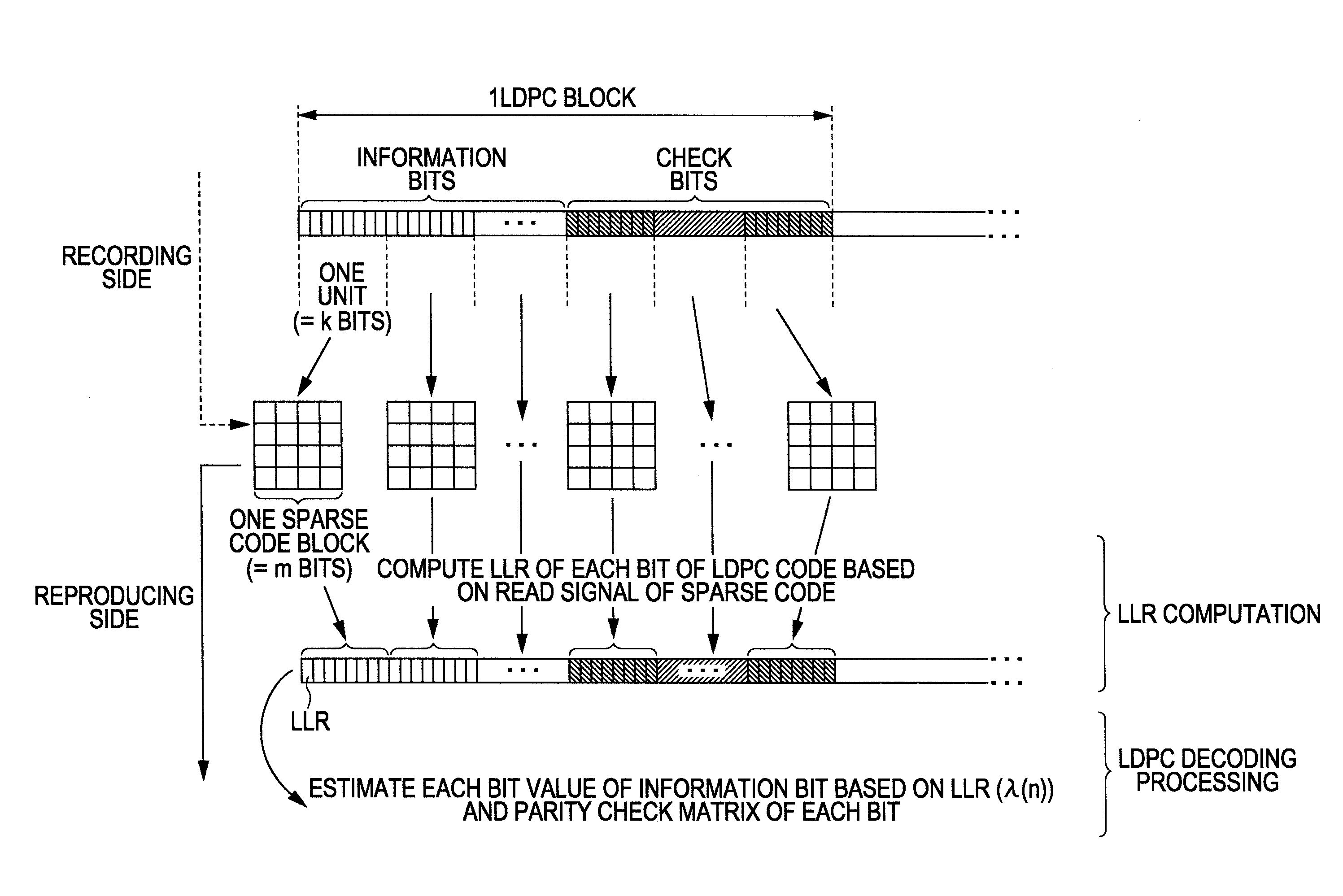
[0401]Now, the LLR computation technique described above is only an example regarding a suitable LLR computation technique in the case of applying LDPC with the hologram recording / reproducing system. As can be understood from the description so far, in the case that sparse code (balance code) is used as recorded modulation code such as the hologram recording / reproducing system, at the time of obtaining the LLR of each bit of an LDPC code string from the read signal, at least the following technique should be used.

[0402]Specifically, a technique is used wherein with regard to the read signal in increments of block data, switching of amplitude rank order to obtain the decoding results thereof is repeated, and at the process thereof, the computation of an LLR is executed so that a smaller (absolute) value is given as an LLR to a bit of which the value has been inverted at the time of initial switching of amplitude ran...

second embodiment

3. Second Embodiment

3-1. Mapping Technique Serving as Second Embodiment

[0490]Next, a second embodiment will be described. The second embodiment is to compute an evaluated value used at the time of selecting the optimal mapping pattern using a technique different from the case of the first embodiment. Specifically, with the second embodiment, an evaluated value computed as the “sum of each Hamming distance of a set of k-bit data patterns correlated to each of sets of block data of which “the Hamming distance is 2” with 2k block data groups used for the mapping” is computed as the “sum of squares of each Hamming distance of a set of k-bit data patterns correlated to each of sets of block data of which “the Hamming distance is 2” with 2k block data groups used for the mapping“.

[0491]Note that, with the second embodiment as well, the configuration of the recording / reproducing device is the same as in the case of the first embodiment, and accordingly, redundant description thereof will b...


PUM


Abstract

A data modulating device includes: an LDPC encoding unit configured to execute LDPC encoding; and a balance encoding unit configured to input a data string subjected to encoding by the LDPC encoding unit as data to be encoded, and convert k bits of this data to be encoded into balance code made up of m-bit block data; with the balance encoding unit executing balance encoding of said data to be encoded using a data conversion table subjected to mapping so that a set of the k-bit data patterns of which the Hamming distance is 1 corresponds to a set of block data of which the Hamming distance is 2.

Description

[0001]The present application claims priority to Japanese Patent Application JP 2009-028381 filed in the Japan Patent Office on Feb. 10, 2009, the entire content of which is hereby incorporated by reference.BACKGROUND OF THE INVENTION[0002]1. Field of the Invention[0003]The present invention relates to a data modulating device and method thereof for obtaining recorded modulation code using block data by performing balance encoding after LDPC encoding.[0004]2. Description of the Related ArtHologram Recording / Reproducing Method[0005]As disclosed in Japanese Unexamined Patent Application Publication No. 2007-79438 for example, a hologram recording / reproducing method for executing recording of data using a hologram format has been in common use. Other examples of the related art include that disclosed in Japanese Unexamined Patent Application Publication Nos. 2007-188576 and 2005-302079. With the hologram recording / reproducing method, at the time of recording, signal light to which spat...

Claims


Application Information

Patent Timeline
Patent Type & Authority Applications(United States)
IPC IPC(8): H03M13/29G06F11/10
CPCH03M5/145H03M13/1111H03M13/63H03M13/1515H03M13/2906H03M13/15
Inventor HARA, MASAAKI
Owner SONY CORP
Why Eureka
Try Eureka