Vacuum adsorption control mechanism device, film pasting device, method of pasting film, and display device

a control mechanism and vacuum adsorption technology, applied in mechanical control devices, process and machine control, instruments, etc., can solve problems such as complicated structure, difficult structure of blowing air, and complicated apparatus structure, and achieve accurate bonding of films to bonding objects, simple structure

Active Publication Date: 2010-08-19
NEC LCD TECH CORP
View PDF4 Cites 19 Cited by
  • Summary
  • Abstract
  • Description
  • Claims
  • Application Information

AI Technical Summary

Benefits of technology

[0016]According to the present invention, there can be provided a vacuum suction control mechanism apparatus capable of accurately bonding a film to a bonding object with a simple structure.

Problems solved by technology

Thus, the structure is problematically complicated.
Furthermore, a structure for blowing air at the time of attraction or bonding complicates the structure of an apparatus.
Moreover, the air blow may cause dust or air to be mixed on a bonding surface.
Thus, there is a problem that the bonding accuracy may be lowered.

Method used


Image

  • Vacuum adsorption control mechanism device, film pasting device, method of pasting film, and display device
  • Vacuum adsorption control mechanism device, film pasting device, method of pasting film, and display device
  • Vacuum adsorption control mechanism device, film pasting device, method of pasting film, and display device

Examples


example

[0139]The present invention will specifically be described below based on an example.

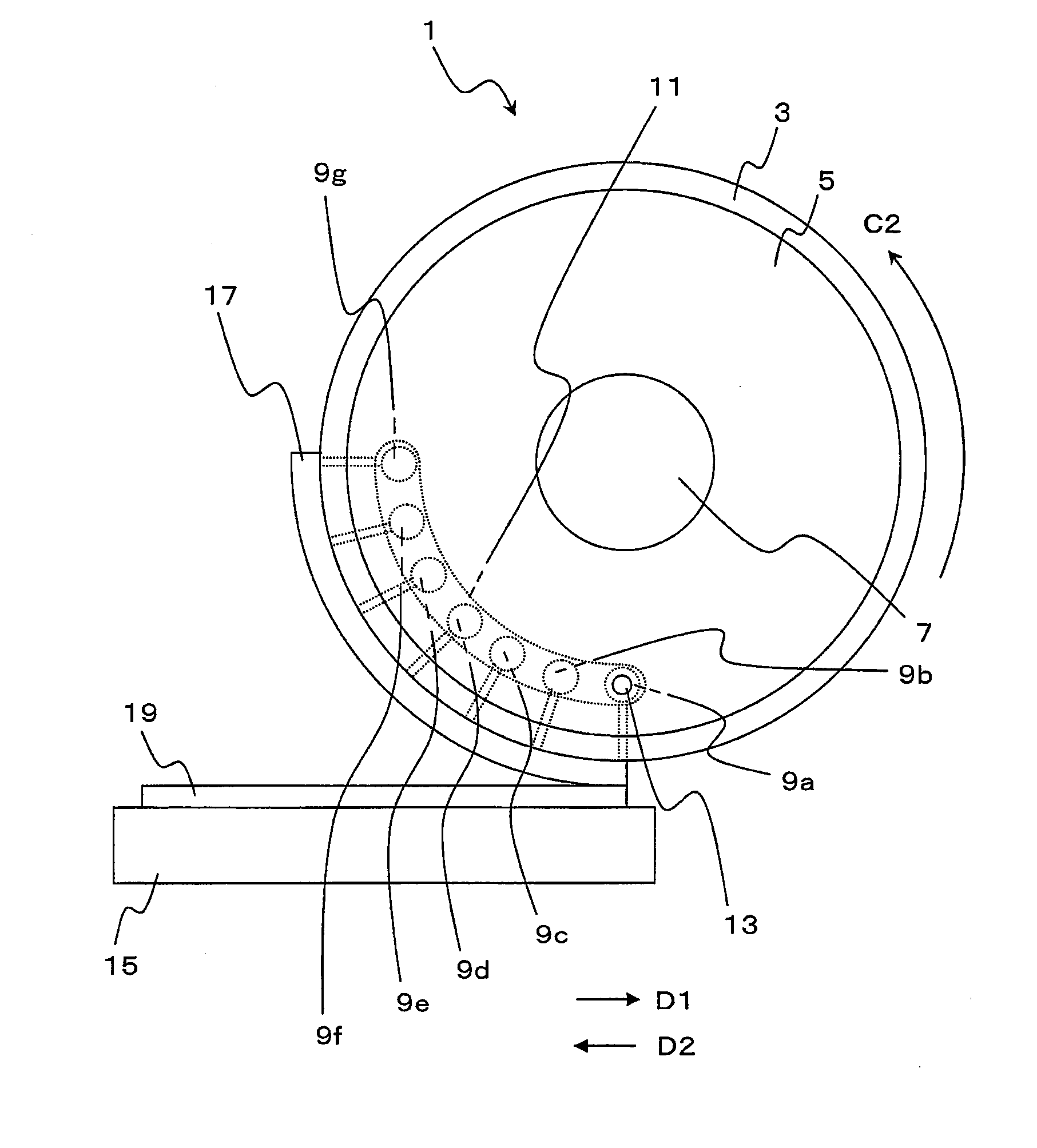
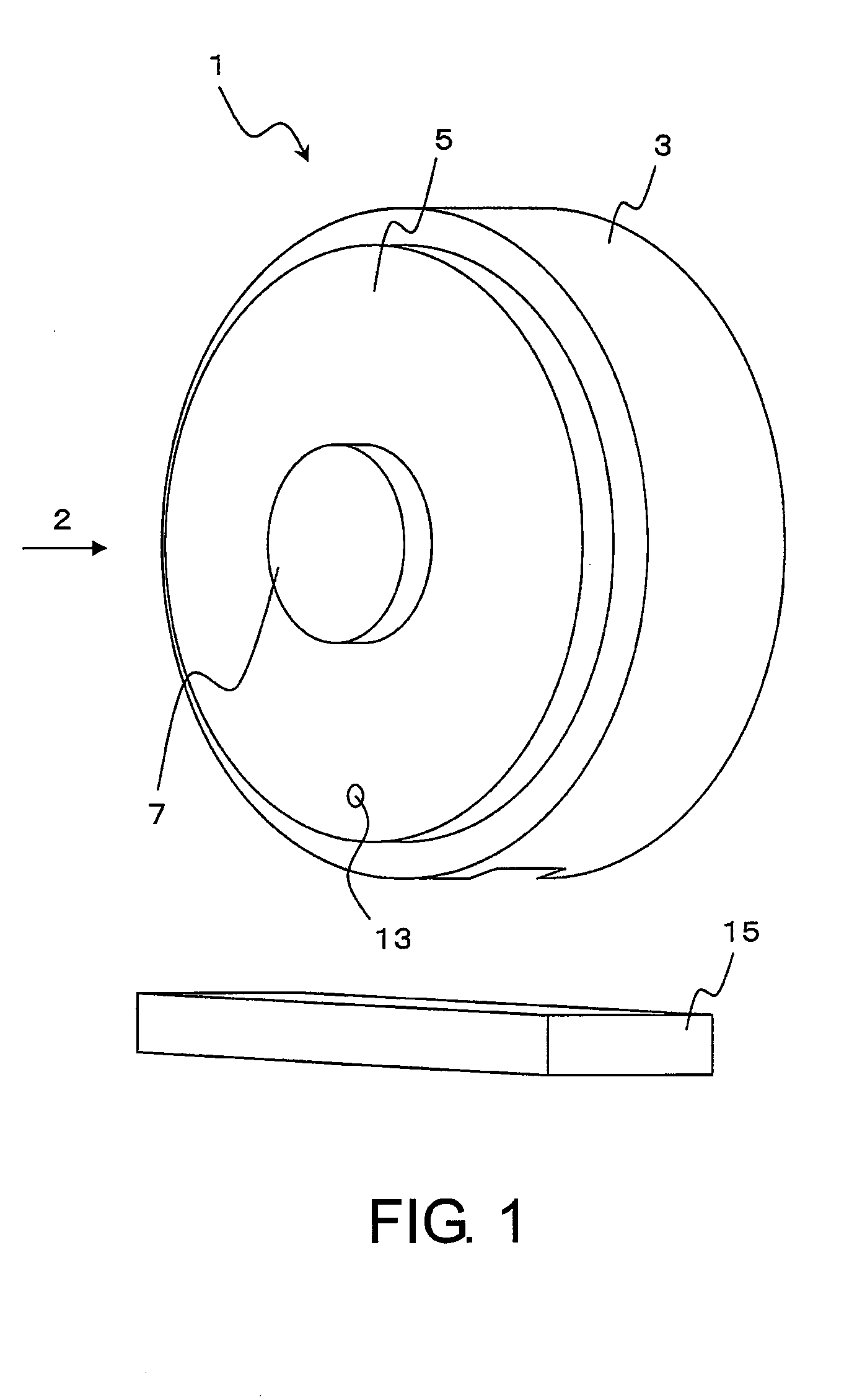
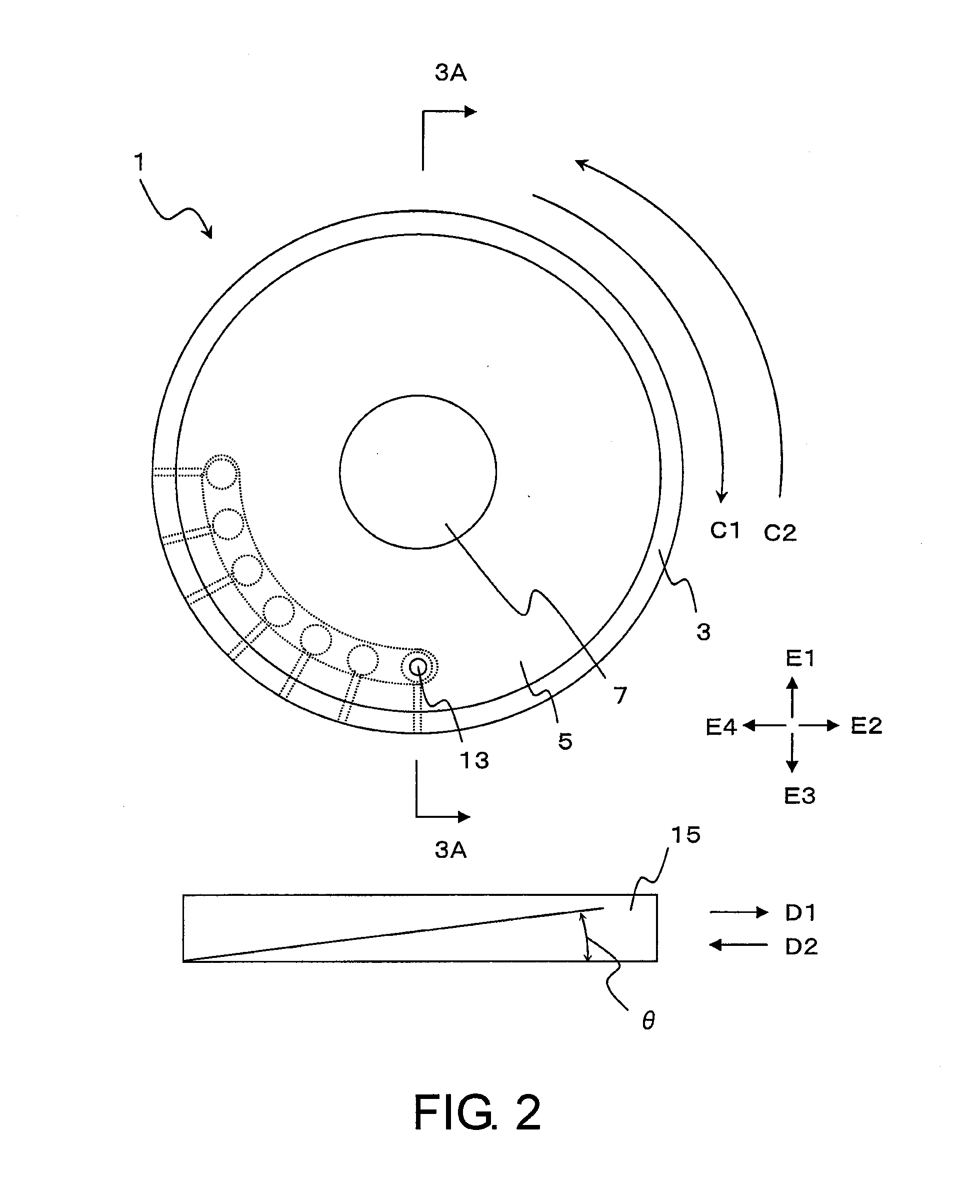
[0140]In an example of the present invention, a film bonding apparatus 1 shown in FIG. 1 was prepared. A polarization film was bonded to a glass substrate 19 comprising a diagonal of 2 inches to 60 inches.

[0141]The polarization film used for bonding had a surface roughness such that 0.3 μm≦Ra≦3.0 μm. The thickness of the polarization film was in a range of from 0.1 mm to 0.5 mm.

[0142]Furthermore, a suction force of each suction hole at the time of bonding was set in a range of from about 2.0×10⁴ Pa to about 4.9×10⁴ Pa.

[0143]As a result, it was confirmed that the polarization film did not fall off from the bonding head 3 during the bonding and that there is no trouble in the slide of the polarization film at the time of the bonding.

[0144]In the aforementioned embodiment, the present invention is applied to an apparatus for bonding a polarization film to a liquid crystal display substrate. However, th...


PUM

PropertyMeasurementUnit
diameteraaaaaaaaaa
diameteraaaaaaaaaa
suctionaaaaaaaaaa

Abstract

An object of the present invention is to provide a vacuum suction control mechanism apparatus capable of accurately bonding a film to a bonding object with a simple structure. A vacuum suction control mechanism apparatus according to the present invention includes a first member including a plurality of suction holes formed in a surface thereof, the plurality of suction holes being connectable to a decompression source, and a second member capable of contacting the plurality of suction holes, the second member being movable relative to the first member, wherein the second member includes connecting member connecting some of the suction holes, the number of which corresponds to a relative position between the first member and the second member, to the decompression source.

Description

BACKGROUND ART[0001]The present invention relates to a vacuum suction control mechanism apparatus, a film bonding apparatus comprising a vacuum suction mechanism, a film bonding method using a film bonding apparatus, and a display apparatus manufactured by a film bonding method.[0002]A display apparatus using liquid crystal or the like is formed by filling liquid crystal or the like between a pair of substrates such as glasses comprising electrodes for display and bonding a polarization film on a surface of one of the substrates.[0003]Apparatuses for bonding a film on a substrate comprise various types of structures. Some apparatuses use a bonding unit (bonding head) comprising suction holes formed in a surface thereof as shown in Patent Document 1.[0004]Specifically, as described at paragraph [0028] of Japanese laid-open patent publication No. 2001-42315 (Patent Document 1), a suction surface of a film support 22, which comprises a curved shape, is formed by a plate comprising a pl...

Claims


Application Information

Patent Timeline
Patent Type & Authority Applications(United States)
IPC IPC(8): B29C63/20
CPCB29C63/024Y10T156/1033B32B38/1858B32B2457/20B65H37/04B65H2406/3314B65H2406/361B65H2701/1752B65H2801/61G02F1/1303G02F1/133528B65H2406/3612Y10T156/1744Y10T156/1773Y10T156/1062B32B37/0053Y10T156/10
Inventor KODERA, HIDEKI
Owner NEC LCD TECH CORP
Why Eureka
Try Eureka