

Fluid-insulated electrical apparatus
- Summary
- Abstract
- Description
- Claims
- Application Information
AI Technical Summary
Benefits of technology
Problems solved by technology
Method used
Image

Examples
first embodiment
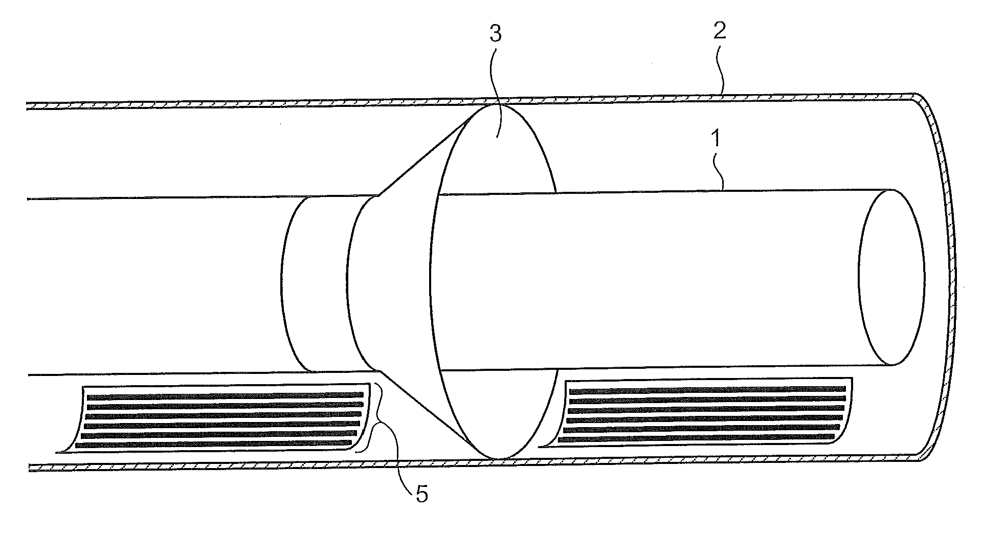
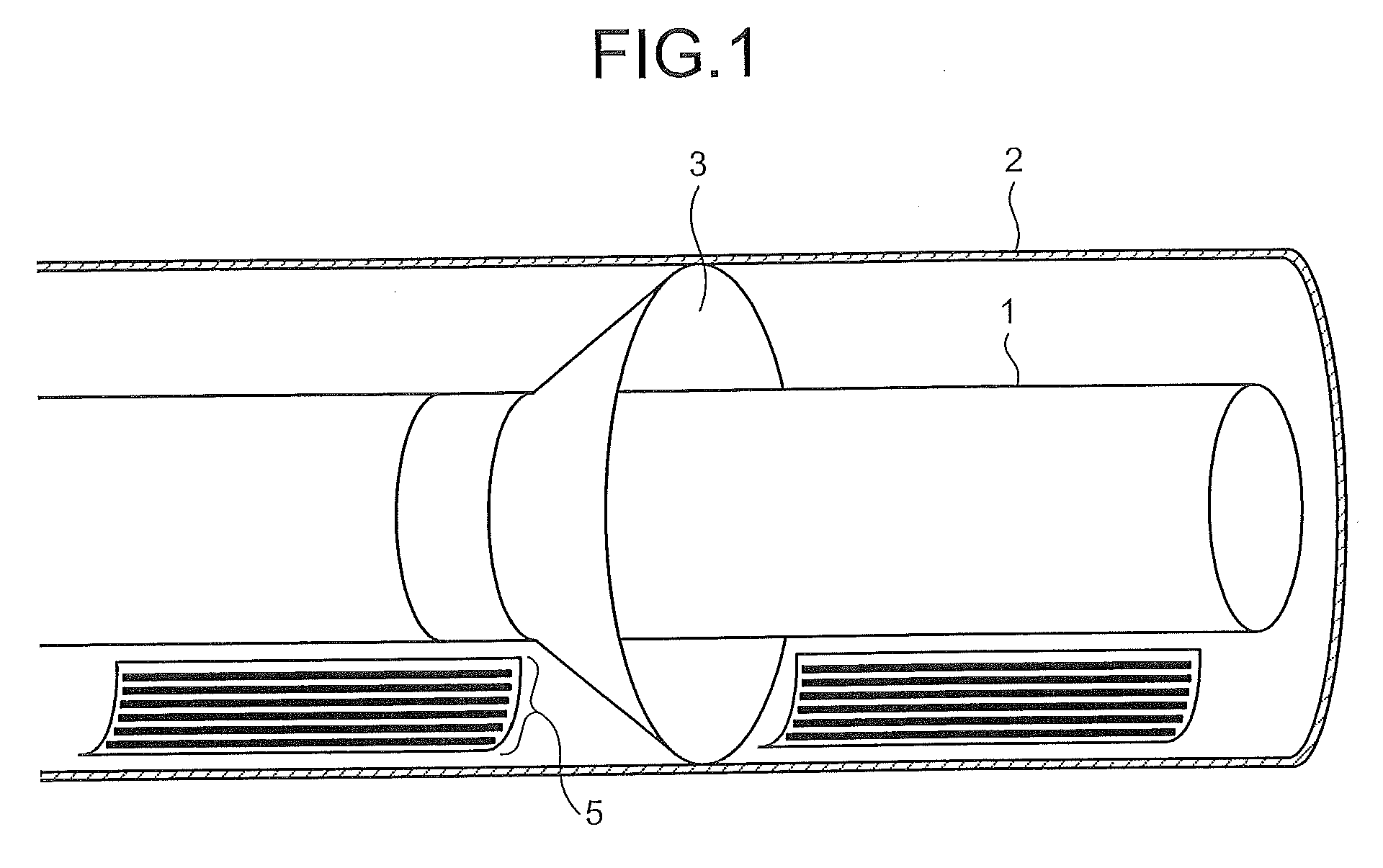
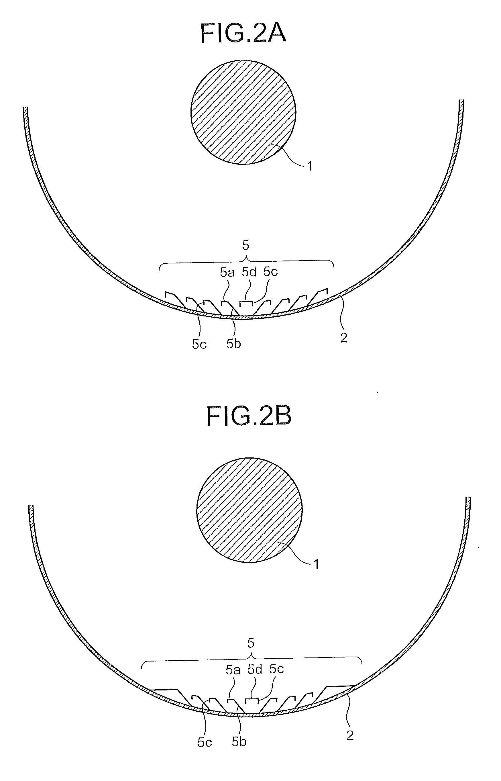
[0025]FIG. 1 is a perspective view of the internal configuration of a fluid-insulated electrical apparatus according to the present invention and FIG. 2A is a front cross-sectional view of the fluid-insulated electrical apparatus shown in FIG. 1. FIG. 3A is a perspective view of a trap apparatus 5 shown in FIG. 1 and FIG. 4 is an enlarged front view of the trap apparatus 5 for explaining movement of a foreign metal substance in the trap apparatus 5. FIG. 5 is an enlarged front view of the trap apparatus 5 for explaining a groove width Ws, a width Wr of a head top portion 5a, a distance H between an inner wall of a grounded tank 2 and the head top portion 5a, a length L of an inclined surface 5b, and a bending angle θ in the trap apparatus 5.
[0026]As shown in FIG. 1, the fluid-insulated electrical apparatus includes the grounded tank 2, a conductor 1, an insulating spacer 3, and the trap apparatus 5. The grounded tank 2 is, for example, cylindrical in shape. The grounded tank 2 is an...
second embodiment
[0050]In the present invention, the trap apparatus 5 is manufactured from one metal plate by a press process. A shearing process and a bending process are performed using a press process, so that a shape having a complicated cross-section can be easily formed, the manufacturing process time can be reduced, and manufacturing costs can be reduced. Accordingly, it becomes easy to manufacture a large-sized trap apparatus, and as such, the grounded tank 2 can be installed over a greater area, whereby the trapping rate of foreign metal substances can be increased.
[0051]Because the trap apparatus 5 can be manufactured from a thin metal plate by a press process, it is lightweight and easy to handle. Even in the case in which the trap apparatus 5 is installed in the large-sized grounded tank 2, because of its light weight, it can be easily attached to the existing grounded tank 2 without any need for additional labor. The chance of a flashover accident caused by a foreign metal substance can...
third embodiment
[0057]In reality, it is difficult to exchange electrostatic charges between a foreign metal substance that moves on the inner surface of the grounded tank 2 that is coated with the insulating coating material 11 and the grounded tank 2, and thus the foreign metal substance's movement is not easily suppressed. However, in the third embodiment, due to the above-described configuration, the foreign metal substance loses its electrostatic charge in the trap apparatus 5 which is electrically connected to the grounded tank 2 and any movement in the vertical direction is transformed into a movement in the horizontal direction by the inclined portion 5b, and so a foreign metal substance which enters the groove collides with the back surface of the inclined portion 5b and reaches the inner surface of the grounded tank 2 which is coated with the insulating coating material 11. An electric field that can provide levitation force to a foreign metal substance is not formed on the inner surface b...
PUM
 Abstract
Description
Claims
Application Information