Riding work vehicle

Inactive Publication Date: 2010-08-19
KANZAKI KOKYUKOKI MFG
View PDF8 Cites 33 Cited by
  • Summary
  • Abstract
  • Description
  • Claims
  • Application Information

AI Technical Summary

Benefits of technology

[0043]As described above, the riding work vehicle according to the present invention is configured to switch the operational state of the caster wheel between the free traveling stat

Problems solved by technology

However, according to the vehicle discussed in Japanese Patent Application Laid-Open No. 2008-168869, if the steering control wheel driving electric rotary machine and the steering actuator are in a deactivated state, the steering control wheel driving electric rotary machine and the steering actuator apply a significant amount of load to the caster wheels when the caster wheels are forcibly rotated for traveling or steering by the driving force of the main driving wheels.
However, the above described Japanese Patent Application Laid-Open No. 2008-168871 has no mention of any mechanism for pre

Method used


Image

  • Riding work vehicle
  • Riding work vehicle
  • Riding work vehicle

Examples


first embodiment

of the Present Invention

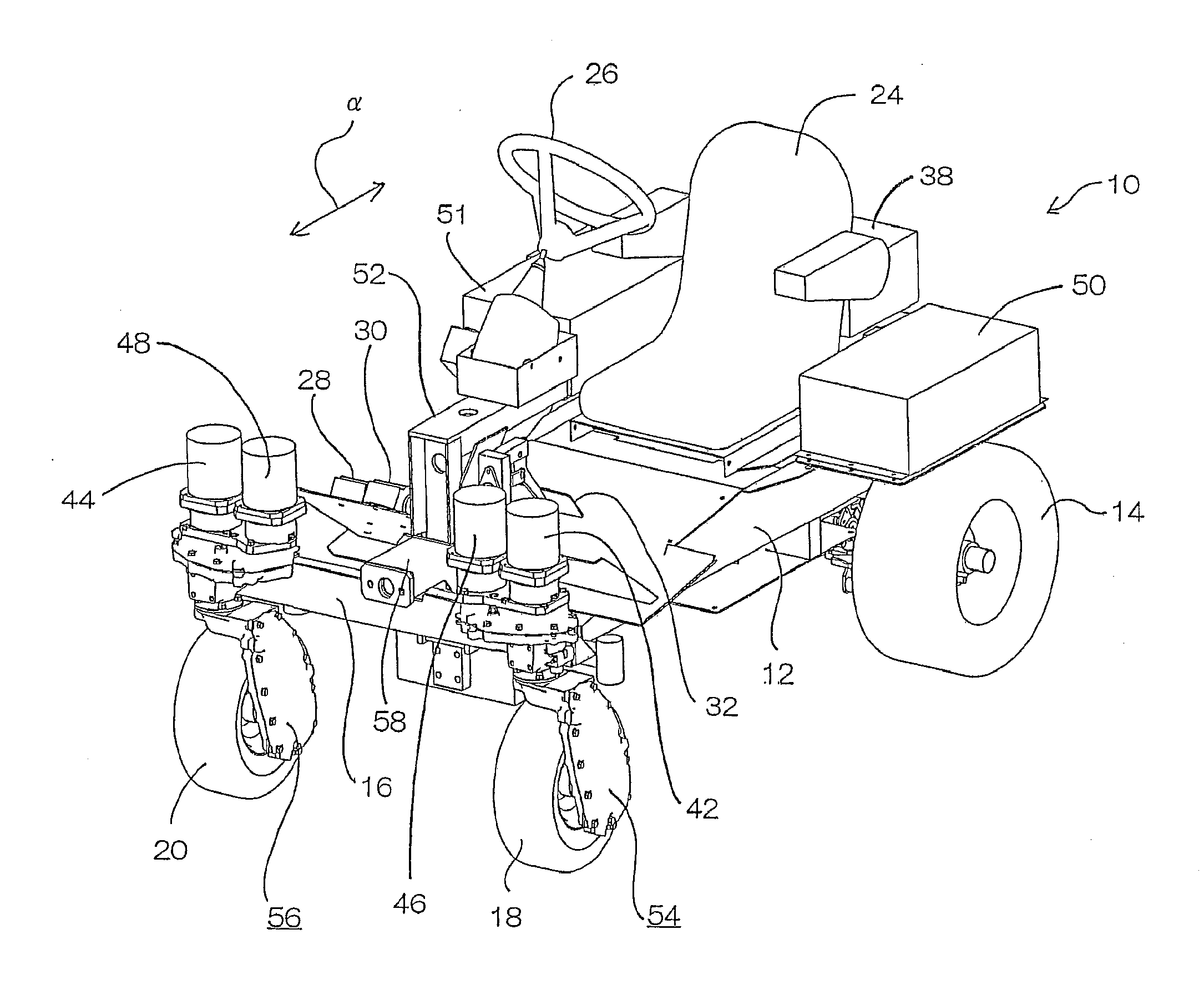
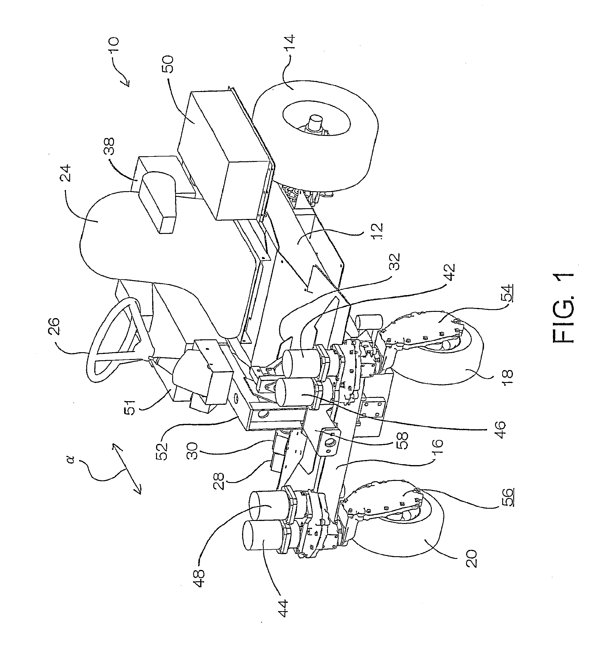
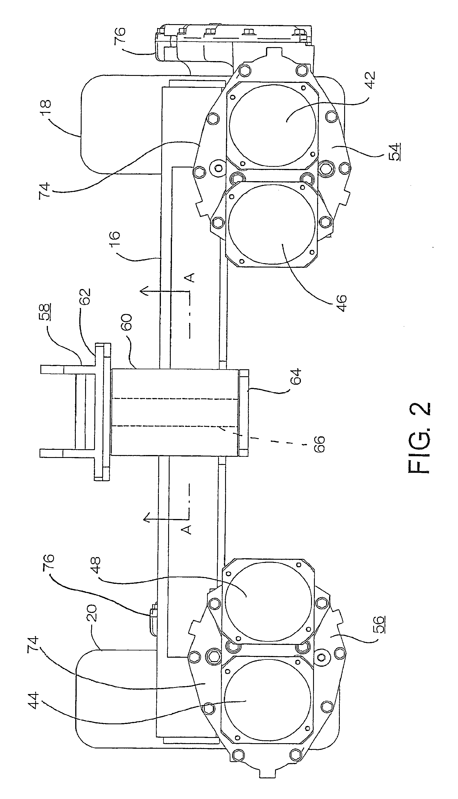
[0065]A first embodiment of the present invention is described below in detail with reference to attached drawings. FIG. 1 is a perspective view illustrating a configuration of a lawnmower vehicle, which is a riding work vehicle according to the first embodiment of the present invention. FIG. 2 is a plan view illustrating a swing arm and caster wheel support units attached to each end of the swing arm as illustrated in FIG. 1. FIG. 3 is a front view illustrating the swing arm and the caster wheel support unit illustrated in FIG. 2. FIG. 4 is a side view illustrating a swing arm and one caster wheel support unit, seen from the vehicle illustrated in FIG. 1. FIG. 5 is an enlarged cross-sectional view taken along a line A-A illustrated in FIG. 2. FIG. 6 is a side view illustrating one caster wheel support unit, seen from the vehicle illustrated in FIG. 1. FIG. 7 is a cross-sectional view taken along a line B-B illustrated in FIG. 6. FIG. 8 is a cross-sectional v...

second embodiment

of the Present Invention

[0171]Next, a second embodiment of the present invention is described below. A lawnmower vehicle that can serve as a riding work vehicle according to the present embodiment has a fundamental configuration similar to that of the lawnmower vehicle 10 according to the first embodiment described with reference to FIG. 1 to FIG. 16. In the following description, components similar to or corresponding to those illustrated in FIG. 1 to FIG. 16 are denoted by the same reference numerals. In the present embodiment, the traveling system clutch 92 is a one-way clutch or a two-way clutch, although it was described as an electromagnetic clutch in the first embodiment with reference to FIG. 8. Similarly, the steering system clutch 94 is a two-way clutch (i.e., not the electromagnetic clutch). These clutches 92 and 94 can be disposed at appropriate positions that are similar to or may be different from the positions described in the first embodiment.

[0172]However, it is des...


PUM


Abstract

A riding work vehicle includes right and left wheels, at least one caster wheel, and a working machine. The lawnmower vehicle further includes traveling motor, steering motor, a traveling system clutch, and a steering system clutch. The traveling system clutch is configured to disable transmission of the rotational force from an axle of the caster wheel to the traveling motor in a state where the traveling motor is deactivated. The steering system clutch is configured to disable transmission of the rotational force from a steering shaft for the caster wheel to the steering motor in a state where the steering motor is deactivated.

Description

PRIORITY INFORMATION[0001]The present invention claims priority from Japanese Patent Application No. 2009-30949 filed on Feb. 13, 2009, which is hereby incorporated herein in its entirety.BACKGROUND[0002]1. Technical Field[0003]The present invention relates to a riding work vehicle, which includes right and left wheels that are operable as main driving wheels and respectively driven independently for traveling, at least one caster wheel that is operable as a steering wheel whose operational state is selectable between free traveling and forced traveling and also between free steering and forced steering, and a working machine that is operable for work on the ground.[0004]2. Related Art[0005]A work vehicle equipped with a working machine is available for work on the ground, such as a conventionally known lawn mower, farm tractor, or the like. The work vehicle can include right and left wheels that are operable as main driving wheels and respectively driven independently for traveling...

Claims


Application Information

Patent Timeline
IPC IPC(8): B60K17/30
CPCB60K7/0007B60K17/30B60Y2200/223B62D5/0418Y02T10/648B62D9/00B60L11/1877Y02T10/7005Y02T10/705B62D7/023B60L50/66Y02T10/70Y02T10/64
Inventor ISHII, NORIHIROEBIHARA, TOMOYUKISASAHARA, KENGO
Owner KANZAKI KOKYUKOKI MFG
Why Eureka
Try Eureka