Sputtering apparatus, double rotary shutter unit, and sputtering method

a sputtering apparatus and shutter technology, applied in the direction of electrolysis components, vacuum evaporation coatings, coatings, etc., can solve the problems of difficult cross-contamination of the above-mentioned double rotary shutter mechanism, and difficulty in discharge or stabilization of low-pressure discharge, etc., to achieve the effect of reliably preventing cross-contamination

Inactive Publication Date: 2010-08-19
CANON ANELVA CORP
View PDF7 Cites 10 Cited by
  • Summary
  • Abstract
  • Description
  • Claims
  • Application Information

AI Technical Summary

Benefits of technology

[0009]The present invention has been made in consideration of the above-described problems, and provides a sputtering apparatus which can more reliably prevent any cross-c

Problems solved by technology

Unfortunately, even the above-mentioned double rotary shutter mechanism may encounter cross-contamination, depending on the sputtering material and the discharge conditions.
In addition, because the sputtering apparatus described in Japanese Patent Laid-Open No. 2005-256112 includes a sputtering gas inlet located at a position relati

Method used


Image

  • Sputtering apparatus, double rotary shutter unit, and sputtering method
  • Sputtering apparatus, double rotary shutter unit, and sputtering method
  • Sputtering apparatus, double rotary shutter unit, and sputtering method

Examples


Embodiment Construction

[0027]One embodiment of the present invention will be described below with reference to the accompanying drawings. Note that members and arrangements, for example, to be described hereinafter are merely examples which embody the present invention and do not limit the present invention, so they can be modified into various forms within the spirit and scope of the present invention, as a matter of course.

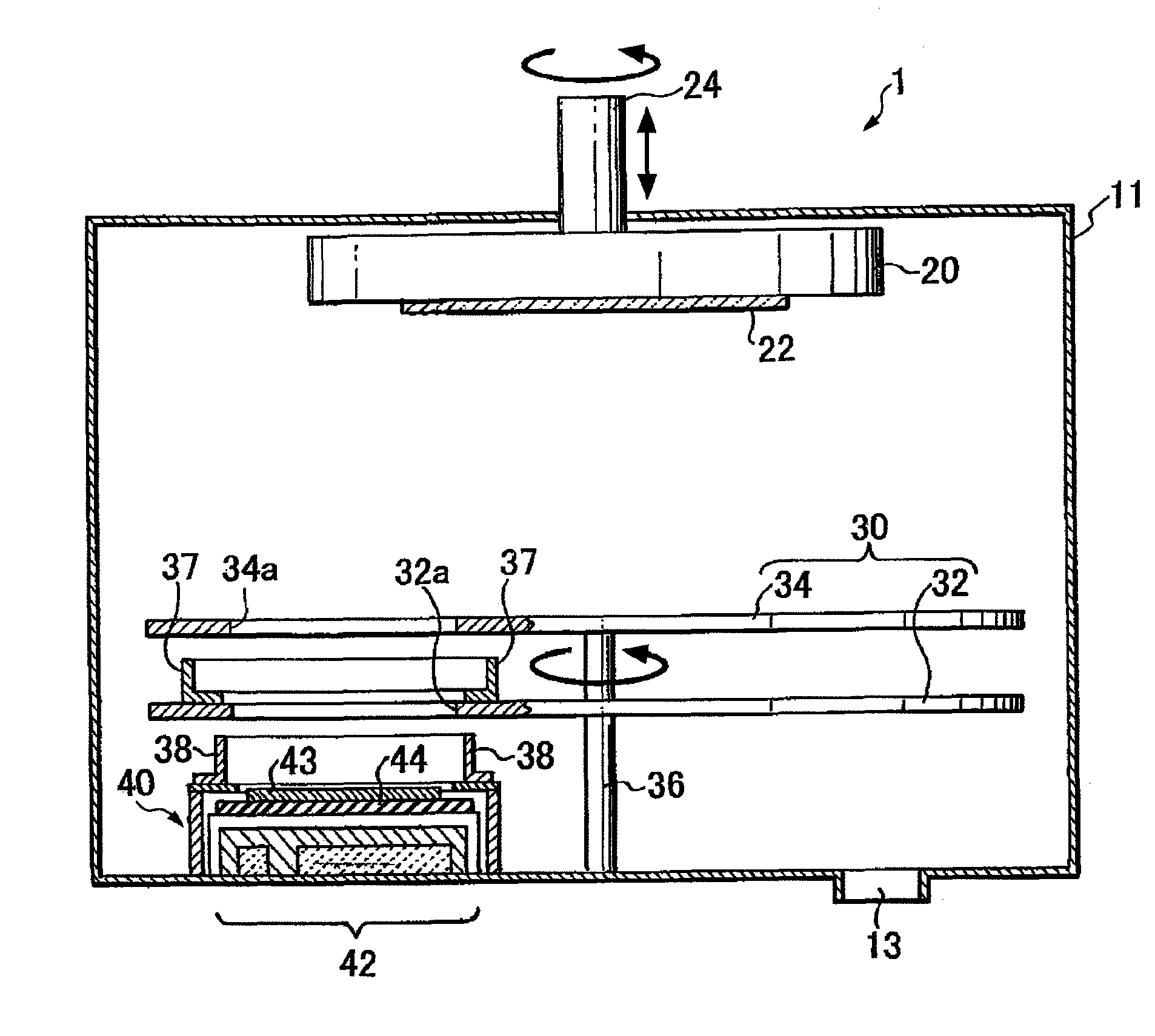
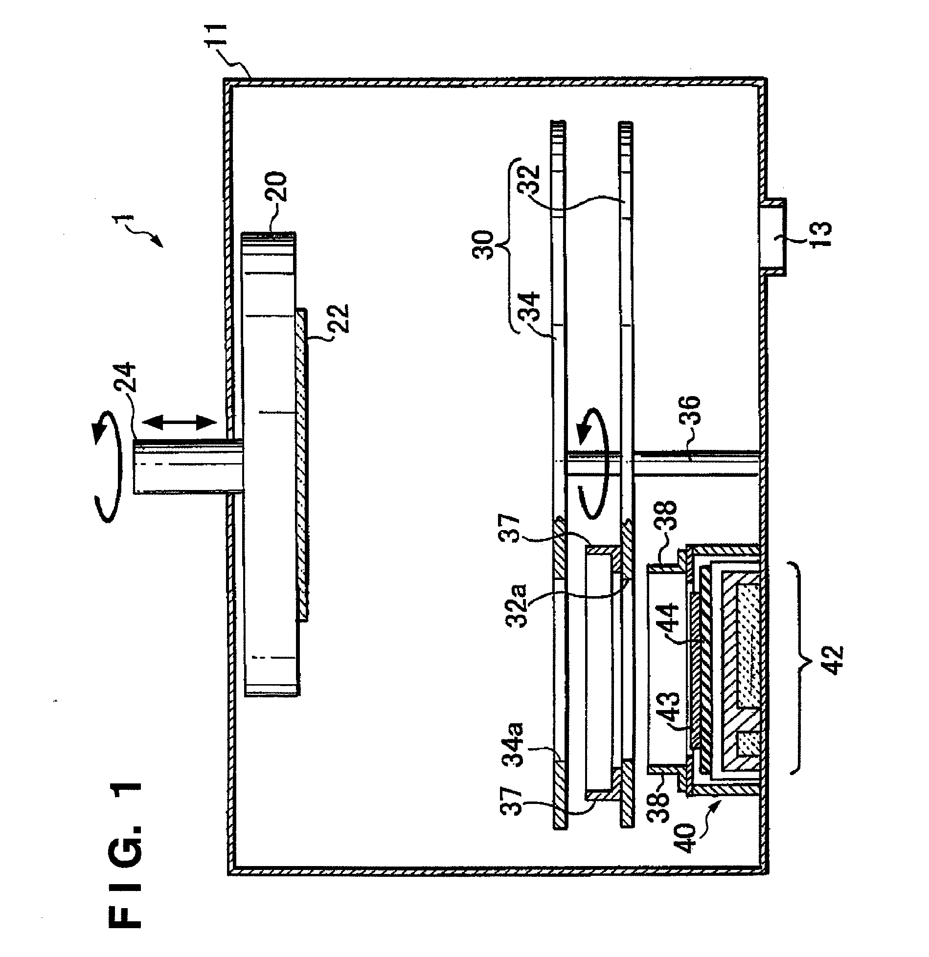
[0028]FIGS. 1 to 3 are views for explaining a sputtering apparatus (multiple cathode sputtering deposition apparatus) according to one embodiment of the present invention, in which FIG. 1 is a schematic sectional view of the sputtering apparatus; FIG. 2 is an enlarged explanatory view of the periphery of a sputtering cathode; and FIG. 3 is an enlarged perspective view of the periphery of the sputtering cathode. Note that some parts are not illustrated in the drawings for the sake of illustrative simplicity.

[0029]A sputtering apparatus 1 according to the present invention includes a pl...


PUM

PropertyMeasurementUnit
Diameteraaaaaaaaaa

Abstract

Two shutter plates form a double rotary shutter mechanism. A cylindrical second deposition shield is interposed between the first shutter plate disposed on the side of a target and the second shutter plate so as to surround a first opening formed in the first shutter plate. A cylindrical first deposition shield is interposed between a sputtering cathode and the first shutter plate so as to surround the front surface region of the target. This makes it possible to prevent a sputtering substance from passing through the gaps between the first shutter plate and the second shutter plate and between the first shutter plate and the sputtering cathode, and to, in turn, prevent generation of any cross-contamination.

Description

BACKGROUND OF THE INVENTION[0001]1. Field of the Invention[0002]The present invention relates to a sputtering apparatus having a structure useful for the manufacture of thin films, a sputtering method, and a double rotary shutter unit and, more particularly, to a sputtering apparatus including a plurality of targets, a double rotary shutter unit mounted in the sputtering apparatus, and a sputtering method.[0003]2. Description of the Related Art[0004]One known sputtering apparatus selects a target to be sputtered from a plurality of targets placed in a vacuum vessel using a double rotary shutter mechanism formed by combining two shutters independently controlled for rotation (see Japanese Patent Laid-Open No. 2005-256112).[0005]The sputtering apparatus (multiple cathode sputtering deposition apparatus) described in Japanese Patent Laid-Open No. 2005-256112 includes four targets placed in a single vacuum vessel, and a double rotary shutter mechanism including two shutter plates which ...

Claims


Application Information

Patent Timeline
IPC IPC(8): C23C14/36
CPCC23C14/3464C23C14/564H01J37/34H01J37/3447H01J37/3429H01J37/3435H01J37/3408
Inventor HIROMI, TAICHIMURAKAMI, TADAAKI
Owner CANON ANELVA CORP
Why Eureka
Try Eureka