Valve Assembly for Dispensing Flowable Materials

a valve and flowable material technology, applied in the direction of liquid handling, instruments, packaged goods, etc., can solve the problems of affecting the accuracy of the dispensing system, and affecting the dispensing quality of liquid, etc., to achieve the effect of straightforward replacement and/or maintenan

Inactive Publication Date: 2010-08-19
FAST & FLUID MANAGEMENT
View PDF12 Cites 10 Cited by
  • Summary
  • Abstract
  • Description
  • Claims
  • Application Information

AI Technical Summary

Benefits of technology

[0015]Thus, the strip will adapt to the shape of the valve member and tolerances of the valve member are less critical. Further, the strip can be replaced relatively easily and, if the strip is relatively thin, e.g. less than 0.5 mm or less than 0.3 mm thick, the openings are less likely to cause caking and / or can be readily cleaned.
[0022]Such modules are suitable for use in dispensers wherein the containers and pumps are stationary and the pumps are connected to a manifold or valve assembly as described above and for use in dispensers comprising a turntable and a single dispensing position. The modules enable relatively straightforward replacement and / or maintenance.

Problems solved by technology

Further, one way in which the precision of dispensing systems is compromised is “dripping”.
Specifically, a “leftover” drip may be hanging from a nozzle that was intended to be added to a previous formulation and, with a new container in place under the nozzle, the drop of liquid intended for a previous formulation may be erroneously added to a new formulation.
Thus, the previous container may not receive the desired amount of the liquid ingredient and the next container may receive too much.
However, these designs often require one or more different motors to operate the wiper element and are limited to use on dispensing systems where the nozzles are separated or not bundled together in a manifold.
Use of a wiper or scraping function would not be practical in a multiple nozzle manifold design as the ingredients from the different nozzles will be mixed by the wiper or scraper which would then also contribute to the lack of precision of subsequently produced formulations.
Another problem associated with dispensing systems that make use of nozzles lies in the dispensing of relatively viscous liquids such as tints, colorants, base materials for cosmetic products, certain pharmaceutical ingredients or other fluid materials having relatively high viscosities.
While some mechanical wiping or scrapping devices are available, these devices are not practical for multiple nozzle manifold systems and the scraper or wiper element must be manually cleaned anyway.

Method used


Image

  • Valve Assembly for Dispensing Flowable Materials
  • Valve Assembly for Dispensing Flowable Materials
  • Valve Assembly for Dispensing Flowable Materials

Examples


Embodiment Construction

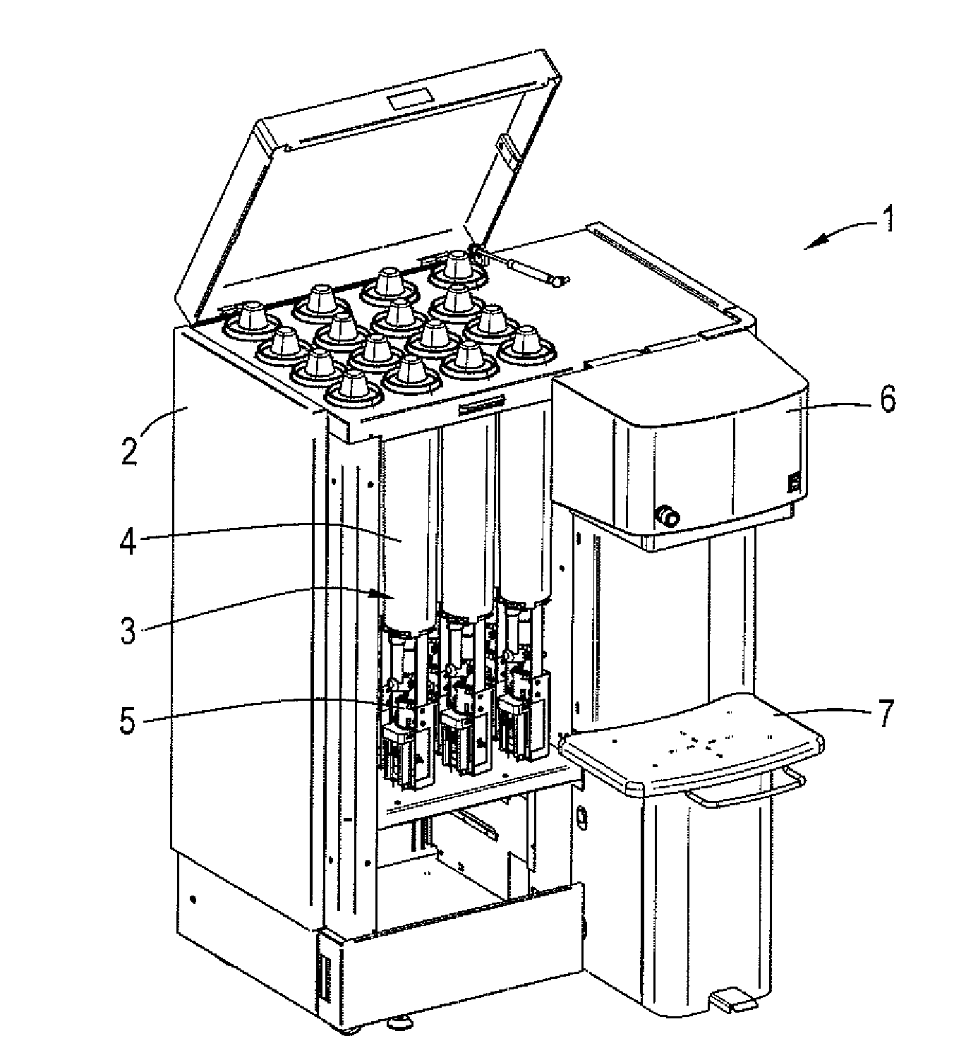
[0030]FIG. 1 illustrates a preferred embodiment of an apparatus 1 for dispensing viscous fluids, such as colorants, base paints, and paint components for decorative purposes, such as masonry paints, and / or industrial purposes. Other examples of viscous fluids that can be dispensed with the apparatus 1 are shampoos, conditioners, foundations, hair dyes, food additives and / or components thereof.

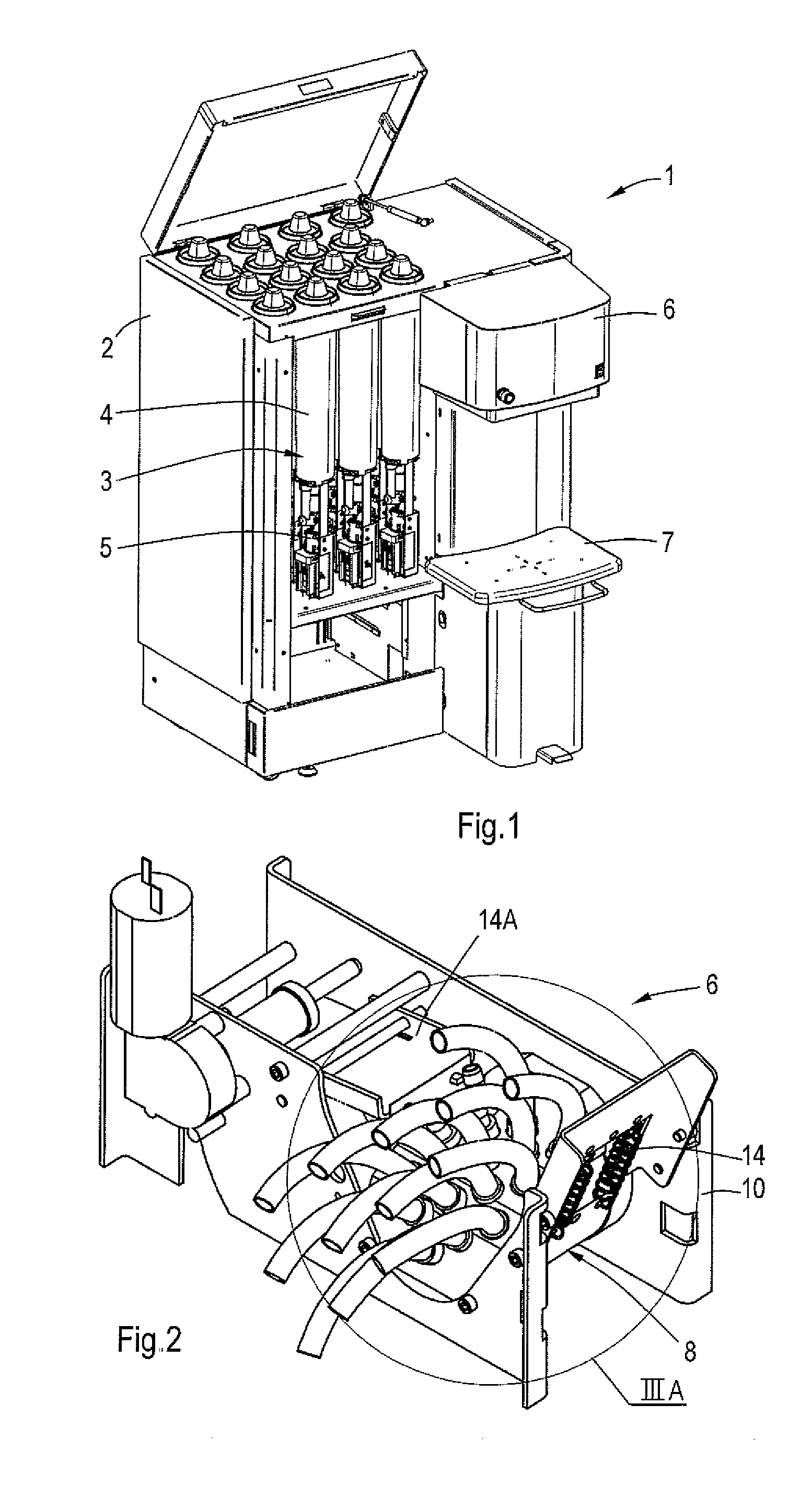
[0031]This particular dispensing apparatus 1 includes a cabinet 2 accommodating a plurality of modules 3 of a container 4 and a pump 5, which modules 3 will be discussed in more detail below. The apparatus 1 further comprises a dispense head 6, shown in FIG. 2, a support 7 for a container located below the dispense head 6 and optionally provided with a weighing device, and electronic equipment (not shown) for driving the components of the apparatus 1. The dispense head 6 in turn comprises a valve assembly 8 for dispensing a plurality of flowable materials.

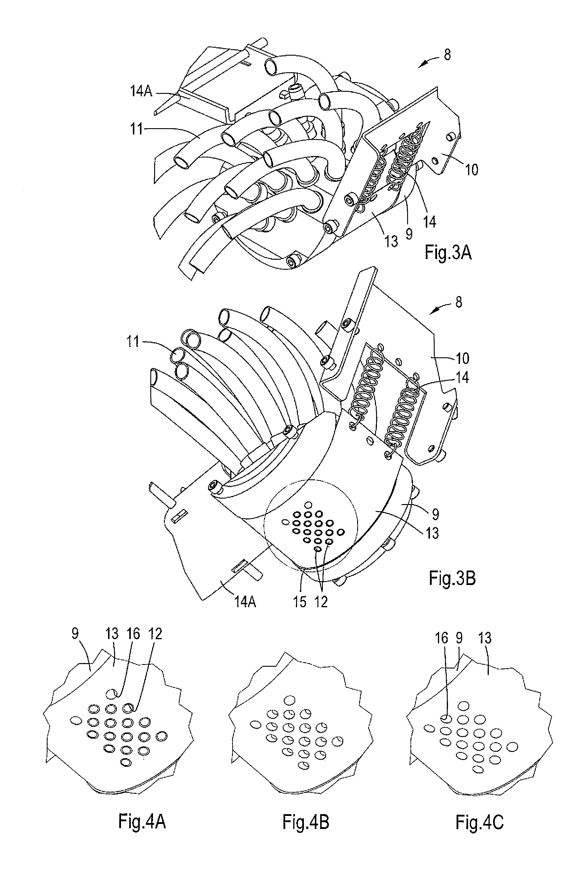
[0032]The valve assembly 8 is shown in ...


PUM

PropertyMeasurementUnit
thickaaaaaaaaaa
thickaaaaaaaaaa
thicknessaaaaaaaaaa

Abstract

A valve assembly for dispensing a plurality of flowable materials, such as viscous fluids or powders, comprising a valve member having a plurality of inlets for the plurality of flowable materials and dispense outlets communicating with the inlets and a closure having one or more openings in a pattern that corresponds to the pattern of at least some of the outlets. The valve member and the closure are movable relative to each other between a closed position in which the outlets are closed and at least one dispensing position in which one or more openings in the closure are at least partially in register with the dispense outlets thus clearing the latter.

Description

TECHNICAL FIELD[0001]A valve assembly and an apparatus are disclosed for dispensing flowable materials, in particular viscous fluids and powders.BACKGROUND OF THE DISCLOSURE[0002]US 2005 / 205154 relates to a closure system for fluid dispensers. The disclosed system is a motorized, articulated system that, in a closed position, provides a cover or closure for a nozzle or nozzle manifold through which one or more fluids are dispensed. In the closed position, the closure element is disposed beneath the nozzle or nozzle manifold and collects any fluid drippings between dispensing operations and also preferably provides a sealing effect. To move the closure system to an open or to a dispense position, a motor is activated which moves the closure element downward before pivoting the closure element away from the nozzle or nozzle manifold.[0003]US 2007 / 0012378 discloses an apparatus for dispensing a plurality of fluids according to one of a plurality of formulas stored in a controller. The ...

Claims


Application Information

Patent Timeline
Patent Type & Authority Applications(United States)
IPC IPC(8): B67D5/40
CPCB01F7/1695B01F7/18F16K47/04F16K11/0655B01F13/1055B01F27/88B01F33/84B01F27/90
Inventor ENGELS, MARCELVOSKUIL, MARCUS JOHANNESALEKSIJOVSKI, GORANVAN LEEUWEN, ROB
Owner FAST & FLUID MANAGEMENT
Why Eureka
Try Eureka