Mounting set, system and method

a technology of mounting set and mounting plate, applied in the direction of engine fuction, aircraft floors, weapons, etc., can solve the problem of providing a metal lug joined to the casing, and achieve the effect of simple and cost-effective system

Active Publication Date: 2013-04-16
ISRAEL AEROSPACE IND
View PDF13 Cites 4 Cited by
  • Summary
  • Abstract
  • Description
  • Claims
  • Application Information

AI Technical Summary

Benefits of technology

[0046]Thus, according to at least some embodiments of the invention a mounting structure is provided that permits attachment of a rocket motor (or other expandable pressure vessel, mutatis mutandis) to a dynamic platform such as an aerospace vehicle, in a manner that accommodates the expansion of the rocket motor that occurs during operation thereof, and / or withstands the stresses associated with operating such a dynamic platform at aggressive g-loads in any direction, in a relatively simple and cost effective manner, and in a manner that may optionally be applied for retrofitting existing stores designs, whether the existing store design does not include any mounting arrangement, or whether the existing stores design already includes a mounting arrangement. Thus, the invention may be applied to a wide range of hardware that has no special provision for mounting to an aerospace vehicle or other suitable dynamic platform, and may be modified in a simple and cost effective manner to enable the same to be transported on the aerospace vehicle or dynamic platform in a similar manner to a standard external stores by matching the one or more mounting sets to the particular size, weight, expansion characteristics and so on of the hardware on the one hand, and the position of the mounting stations onto which it is to be mounted, on the other hand. The mounting sets do not normally require any modification of the hardware, except for example providing suitable rounded edges for applications where the straps of the mounting sets would otherwise need to be abutted over sharp edges, and thus the mounting sets may be removed from the hardware after use, as appropriate, without causing damage.
[0067]The mounting sets are not generally sensitive to manufacturing tolerances, including diameter uniformity of the stores, and thus can lead in some cases to manufacturing cost reductions, where the stores may be manufactured to less stringent tolerances.

Problems solved by technology

However, providing a metal lug joined to the casing may present difficulties when the casing is non-metallic and / or the casing is thin and / or is subject to significant expansion during operation of the stores.

Method used


Image

  • Mounting set, system and method
  • Mounting set, system and method
  • Mounting set, system and method

Examples


Embodiment Construction

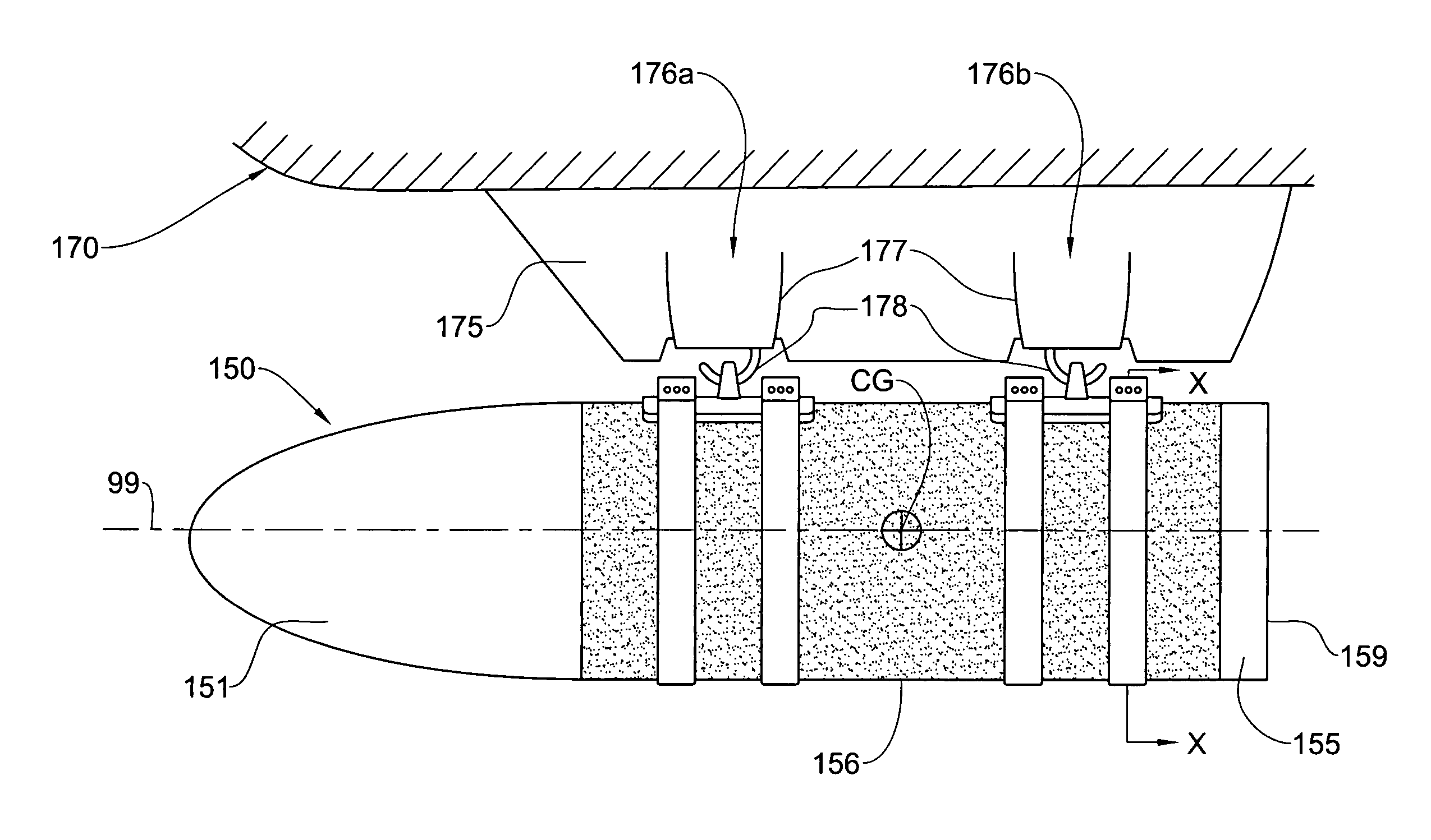
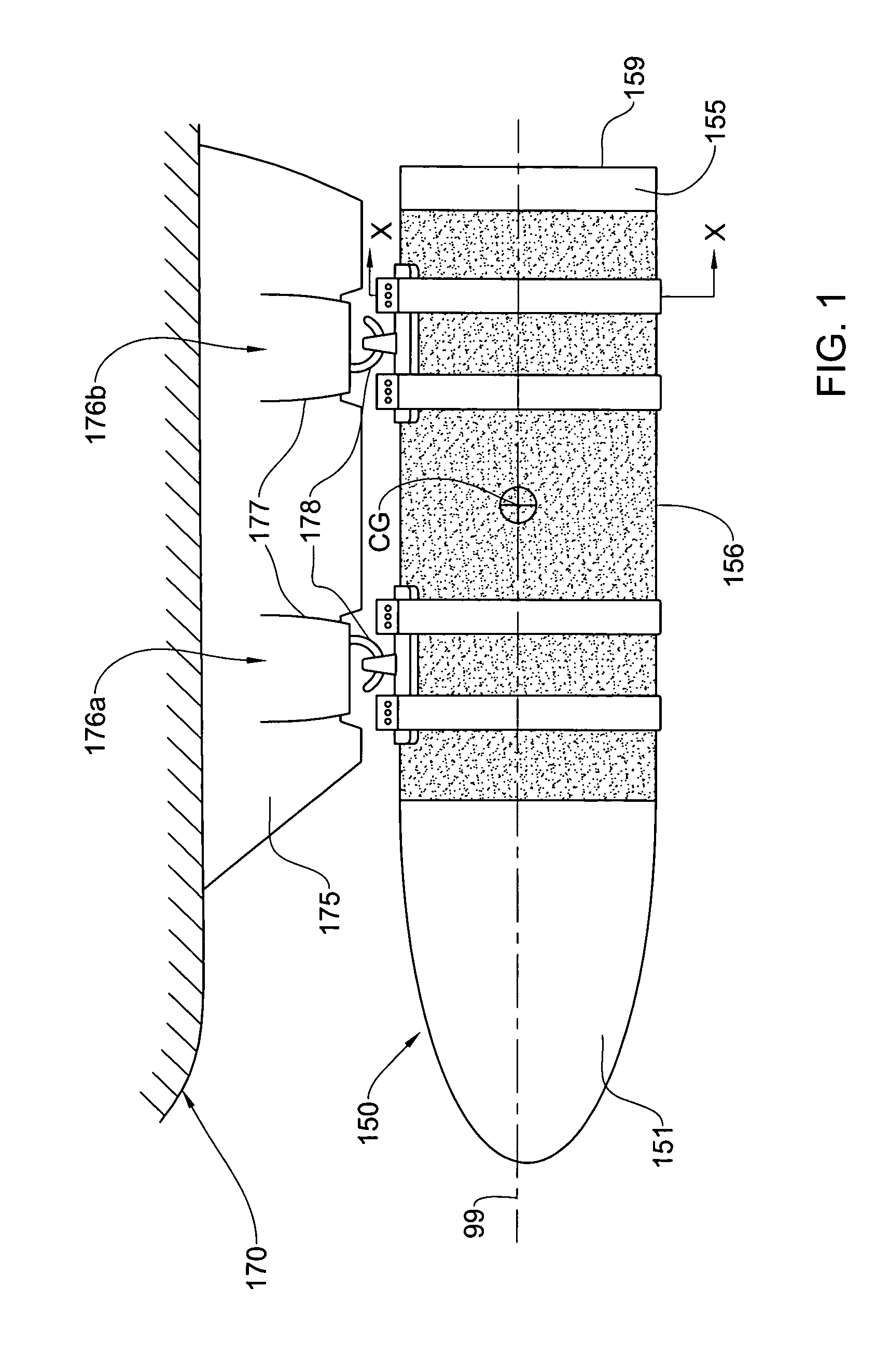
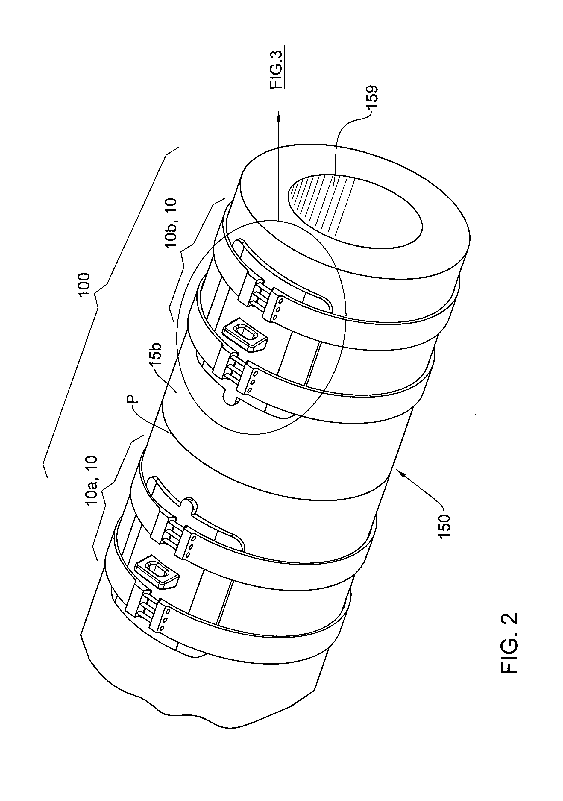
[0079]Referring to FIGS. 1 to 4, a mounting system according to a first embodiment of the invention, generally designated 100, is provided for selectively and releasably engaging a stores 150 with respect to a dynamic platform 170.

[0080]In the first embodiment, and referring particularly to FIG. 1, the dynamic platform 170 comprises a carrier vehicle, in particular an aerospace vehicle, such as for example an aircraft, which may be a manned aircraft of an unmanned air vehicle (UAV), for example, though the invention may be applied, mutatis mutandis, to any other suitable dynamic platform. In this embodiment, the stores 150 may be mounted with respect to a standard mounting structure, or indeed to any other suitable mounting structure, provided in the dynamic platform. By way of example, the mounting structure is that of a standard wing pylon 175, comprising a pair of axially spaced mounting stations 176a, 176b, each station comprising a release shackle 177 having a hook 178 that coo...


PUM


Abstract

A mounting set for use in mounting an external stores to a mounting station of an aerospace vehicle includes a mounting bracket arrangement and a strap arrangement. The bracket arrangement is configured for selective reversible engagement with respect to the mounting station and for cooperating with the strap arrangement. The strap arrangement is configured for securing the bracket arrangement to the stores in load bearing abutment therewith to enable transfer of loads between the stores and the mounting station via said bracket arrangement, in operation of said mounting set. A mounting system is also provided for mounting an external stores to an aerospace vehicle having two or more mounting stations, including a mounting set for each mounting station. Mounting methods are also provided.

Description

FIELD OF THE INVENTION[0001]This invention relates to stores carried on dynamic platforms, in particular rocket propelled missiles and the like carried on air / space vehicles.BACKGROUND OF THE INVENTION[0002]There are a variety of different systems for carrying stores on a dynamic platform such as an aerospace vehicle, and for deploying the stores therefrom. In one commonly used system, the stores are releasably mounted to mounting stations of aircraft, space vehicles and the like by means of lugs integrally formed or permanently fixed on the stores, either externally on pylons, or within a bomb bay or the like, and the lugs may be releasably engaged with release shackles or the like on the carrier vehicle. The lugs are joined to the stores casing in a manner such as to enable it to stand the dynamic loads during operation of the vehicle, and the lugs are provided in the prior art as a unitary item with the stores, limiting use of the particular stores with a particular mounting stat...

Claims


Application Information

Patent Timeline
Patent Type & Authority Patents(United States)
IPC IPC(8): B64D1/12
CPCB64D1/04F02K9/343F41F5/00F42B25/00B64D9/00B64D1/00B64D7/08F05D2260/30F05D2240/90
Inventor SCHNITZER, ISRAEL
Owner ISRAEL AEROSPACE IND
Why Eureka
Try Eureka