Comminuting tool and comminuting device with such a comminuting tool, as well as a method for determining the state of wear of such a comminuting tool

Active Publication Date: 2010-08-19
PALLMANN MASCHFAB GMBH & CO KG
View PDF7 Cites 1 Cited by
  • Summary
  • Abstract
  • Description
  • Claims
  • Application Information

AI Technical Summary

Benefits of technology

[0009]It is therefore an object of the present invention to provide the possibility of being able to determine reliably, simply, and precisely the wear on comminuting tools on a long-term basis.

Problems solved by technology

Only wear in this direction, which defines the main wear direction, affects the gap width to the stator or neighboring rotor and subsequently detrimentally impacts the quality of the comminution.
Instead, the degree of wear results from the distance of the active edge perpendicular to the reference surface.

Method used


Image

  • Comminuting tool and comminuting device with such a comminuting tool, as well as a method for determining the state of wear of such a comminuting tool
  • Comminuting tool and comminuting device with such a comminuting tool, as well as a method for determining the state of wear of such a comminuting tool
  • Comminuting tool and comminuting device with such a comminuting tool, as well as a method for determining the state of wear of such a comminuting tool

Examples


Embodiment Construction

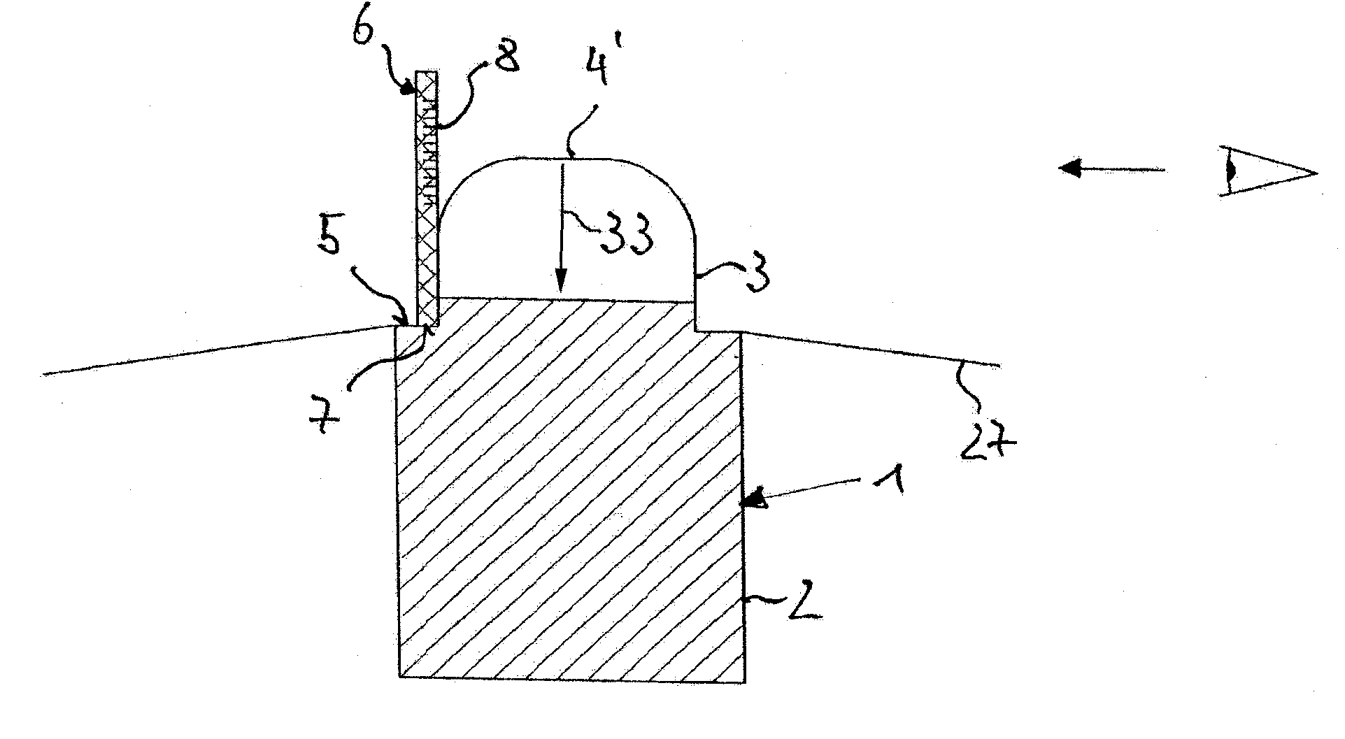
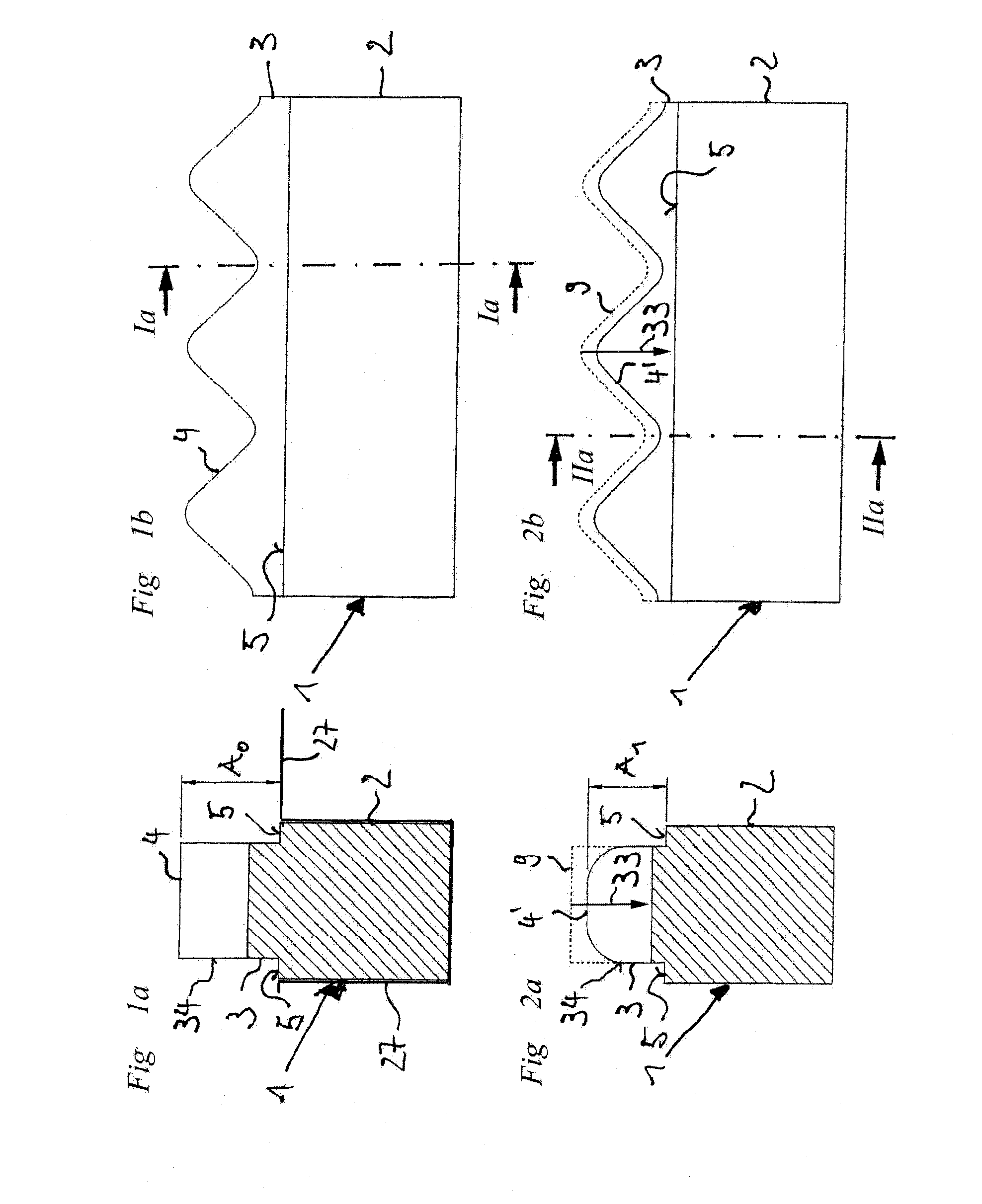
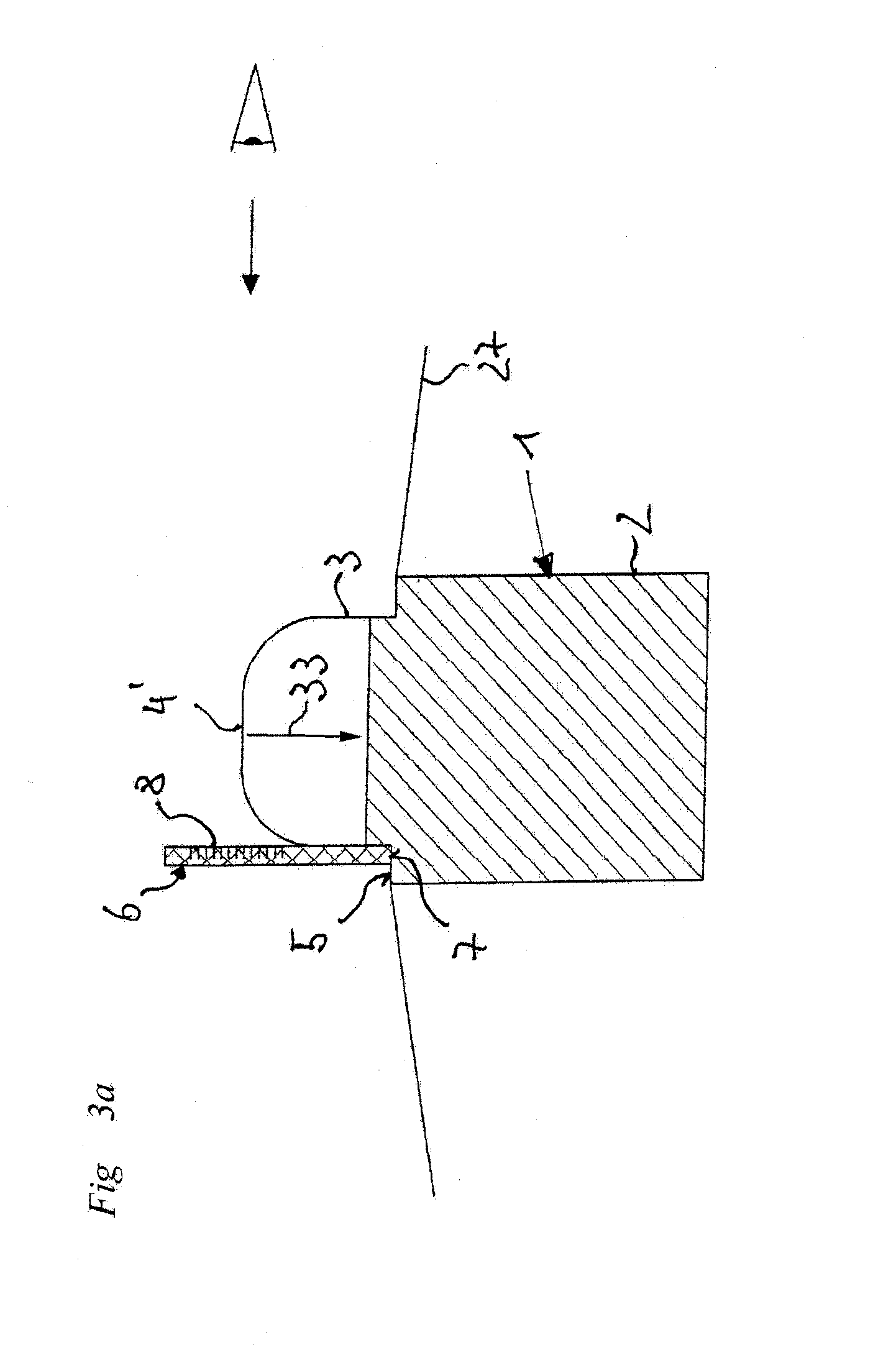
[0029]FIGS. 1a to 2b show a comminuting tool 1 in the form of a shearing tool. Comminuting tool 1 is used for the coarse comminution of feedstock of all types, for example, of scrap wood, used tires, electronic waste, cable waste, and the like. A device in which comminuting tools 1 of this type can be used is described, for example, in the Unexamined German Pat. Appl. No. DE 10 2006 056 542. Stator tools are also disclosed therein, which lie opposite to the comminuting tools of the invention with maintenance of a radial working gap. The comminution between the stator tools and comminuting tools 1 occurs primarily as shearing, tearing, and crushing. The high forces attendant thereto cause high wear.

[0030]Comminuting tool1 shown in FIGS. 1a and b has a rectangular base member 2, which embodies the bearing area for clamping in a complementarily shaped retainer, designated with the reference number 27, in the rotor. The comminution area, active during comminution, in the form of a cutte...


PUM


Abstract

A device for the determination of the state of wear of comminuting tools a comminuting tool, a comminuting device with such a comminuting tool, and a corresponding method. A reference surface is provided on the comminuting tool, the surface from which the distance A0, A1 to the active edges of the comminuting tool can be determined. The degree of wear then results from a comparison of the original distance A0 in an unused comminuting tool with the distance A1 reduced due to wear after a certain period of use. The thereby achieved advantage is that the state of wear can be determined independent of the general wear of the comminuting device. A distortion of the measurement result caused by this is therefore ruled out.

Description

[0001]This nonprovisional application claims priority under 35 U.S.C. §119(a) to German Patent Application No. DE 10 2009 008 642, which was filed in Germany on Feb. 12, 2009, and which is herein incorporated by reference.BACKGROUND OF THE INVENTION[0002]1. Field of the Invention[0003]The present invention relates to a comminuting tool for a comminuting device having a rotor-stator system or rotor-rotor system and to a method for determining the state of wear of a comminuting tool.[0004]2. Description of the Background Art[0005]The conversion of materials into an intermediate or end product, for example, and therefore also the comminution of materials fall within the field of mechanical process engineering. The category of comminuting machines suitable for this purpose also includes devices with a rotor-stator system or rotor-rotor system. Their rotors are edged with comminuting tools, which over the course of rotation are moved past the tools of a stator or second rotor and comminu...

Claims


Application Information

Patent Timeline
IPC IPC(8): B02C23/00
CPCB02C13/28B02C18/18B02C18/06
Inventor PALLMANN, HARTMUT
Owner PALLMANN MASCHFAB GMBH & CO KG
Why Eureka
Try Eureka