Phase mismatch compensation device

a phase difference and compensation device technology, applied in the direction of different amplifiers, amplifiers with semiconductor devices/discharge tubes, low noise amplifiers, etc., can solve the problems of difficult phase difference compensation, slow processing speed, and not exactly 90 degree phase difference between i-channel and q-channel signals

Inactive Publication Date: 2010-08-19
INTEGRANT TECH
View PDF3 Cites 18 Cited by
  • Summary
  • Abstract
  • Description
  • Claims
  • Application Information

AI Technical Summary

Benefits of technology

[0007]In one aspect, a phase mismatch compensation device filtering in-phase channel and quadrature-phase channel analog input signals and outputting I-channel and Q-channel output signals, the phase mismatch compensation device comprises a first low pass filter unit comprising a first OP-amp, a first input unit and a first self-feedback unit, the first input unit transferring the I-channel analog input signal to an input terminal of the first OP-amp, and the first self-feedback unit transferring the I-channel output signal to the input terminal of the first OP-amp; a second low pass filter unit comprising a second OP-amp, a second input unit and a second self-feedback unit, the second input unit transferring the Q-channel analog input signal to an input terminal of the second OP-amp, and the second self-feedback unit transferring the Q-channel output signal to the input terminal of the second OP-amp; and a phase compensation unit comprising a first compensation unit and a second compensation unit, the first compensation unit transferring the Q-channel analog input signal to the input terminal of the first OP-amp, and the second compensation unit transferring the I-channel analog input signal to the input terminal of the second OP-amp.

Problems solved by technology

However, typically, the phase difference between the I-channel and Q-channel signals is not exactly 90 degrees due to the implementation state and external environment of a circuit.
However, if the phase difference between the I-channel and Q-channel signals is large when the phase difference compensation is performed in the digital area, it is difficult to perform the phase difference compensation.
Since complicated digital processing is required in the phase difference compensation, its processing speed is slow.
Further, a pilot signal with a long period is required in estimating the exact phase difference, and therefore, overheads are increased.

Method used


Image

  • Phase mismatch compensation device
  • Phase mismatch compensation device
  • Phase mismatch compensation device

Examples


Embodiment Construction

[0020]Reference will now be made in detail embodiments of the invention examples of which are illustrated in the accompanying drawings.

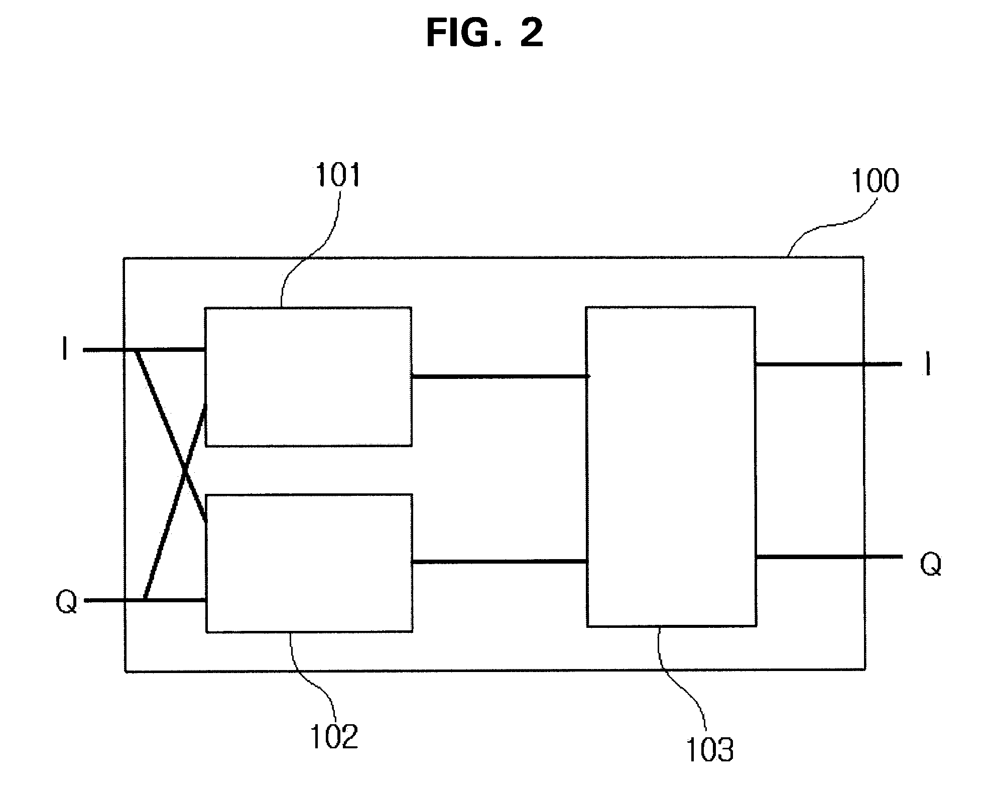
[0021]FIG. 2 is a block diagram of a phase mismatch compensation device applied to a complex bandpass filter according to an embodiment of the present invention. Referring to FIG. 2, the phase mismatch compensation device 100 according to the embodiment of the present invention filters in-phase channel (I-channel) and quadrature-phase channel (Q-channel) analog input signals and then outputs I-channel and Q-channel output signals. Here, phase mismatch compensation device 100 comprises an I-channel phase conversion unit 101 converting the phase of an I-channel output signal using I-channel and Q-channel analog input signals; a Q-channel phase conversion unit 102 converting the phase of a Q-channel output signal using I-channel and Q-channel analog input signals; and a complex filter unit 103 performing filtering. In FIG. 2, a signal is processed by th...


PUM


Abstract

A phase mismatch compensation device comprises a first low pass filter unit, a second low pass filter unit and a phase compensation unit. The first low pass filter unit comprises a first input unit transferring the I-channel analog input signal to an input terminal of a first OP-amp, and the first self-feedback unit transferring the I-channel output signal to the input terminal of the first OP-amp. The second low pass filter unit comprises the second input unit transferring the Q-channel analog input signal to an input terminal of a second OP-amp, and a second self-feedback unit transferring the Q-channel output signal to the input terminal of the second OP-amp. The phase compensation unit comprises a first compensation unit transferring the Q-channel analog input signal to the input terminal of the first OP-amp, and a second compensation unit transferring the I-channel analog input signal to the input terminal of the second OP-amp.

Description

BACKGROUND[0001]1. Field[0002]The present invention relates to a phase mismatch compensation device.[0003]2. Description of the Related Art[0004]FIG. 1 is a view illustrating the structure of a Bluetooth receiver as one example of a low-intermediate frequency (IF) receiver. At the radio frequency (RF) front end, an RF signal is amplified and down-converted to an IF signal. Then, channel selection is performed in an active complex filter. Subsequently, the IF signal is amplitude limited by an amplitude limiter and then demodulated by a frequency shift keying (GFSK) demodulator.[0005]Here, it is preferable that in-phase channel (I-channel) and quadrature-phase channel (Q-channel) signals have an exact phase difference of 90 degrees for the purpose of exact restoration of a signal. However, typically, the phase difference between the I-channel and Q-channel signals is not exactly 90 degrees due to the implementation state and external environment of a circuit. Therefore, a device that ...

Claims


Application Information

Patent Timeline
Patent Type & Authority Applications(United States)
IPC IPC(8): H03F3/45
CPCH03F3/45475H03F2200/294H03F2200/336H03F2203/45594H03F2203/45512H03F2203/45526H03F2203/45528H03F2203/45134
Inventor KIM, SEYEOB
Owner INTEGRANT TECH
Why Eureka
Try Eureka