Antenna system using housings of electronic device and electronic device comprising the same

an electronic device and electronic device technology, applied in the direction of antennas, antenna details, electrical devices, etc., can solve the problems of affecting the performance of the antenna, and affecting the appearance of the electronic device. , to achieve the effect of diversifying the design of the electronic device and reducing the size of the electronic devi

Inactive Publication Date: 2010-08-19
EMW CO LTD
View PDF3 Cites 9 Cited by
  • Summary
  • Abstract
  • Description
  • Claims
  • Application Information

AI Technical Summary

Benefits of technology

[0020]According to the present invention, an antenna that does not occupy the inner space of an electronic device or mar the beauty of the external appearance of the electronic device and an electronic device having the same can be obtained. Furthermore, a diversity antenna or a multiband antenna system can be easily constructed without using an additional antenna element. Moreover, the antenna does not occupy the inner space of the electronic device, and thus the size of the electronic device can be reduced and diversification of the design of the electronic device can be achieved.

Problems solved by technology

Accordingly, installation of an antenna inside the electronic device prevents the inner space of the electronic device from being effectively used and hinders a reduction in the size of the electronic device.
Furthermore, the performance of the antenna is abruptly deteriorated due to a housing when the housing is made of a metal.
When an external antenna is used for the electronic device, the antenna is projected from the electronic device and thus the beauty of the external appearance of the electronic device is spoiled.
In the case of a detachable antenna, a user should carry the antenna and the antenna has the same problem as that of the external antenna when the detachable antenna is combined with the electronic device.

Method used


Image

  • Antenna system using housings of electronic device and electronic device comprising the same
  • Antenna system using housings of electronic device and electronic device comprising the same
  • Antenna system using housings of electronic device and electronic device comprising the same

Examples


Embodiment Construction

[0029]The present invention will now be described more fully with reference to the accompanying drawings, in which exemplary embodiments of the invention are shown. The invention may, however, be embodied in many different forms and should not be construed as being limited to the embodiments set forth herein. In the specification, an electronic device is referred to as a device having a wireless communication function and including a housing, such as a PDA, a notebook computer and a desktop computer.

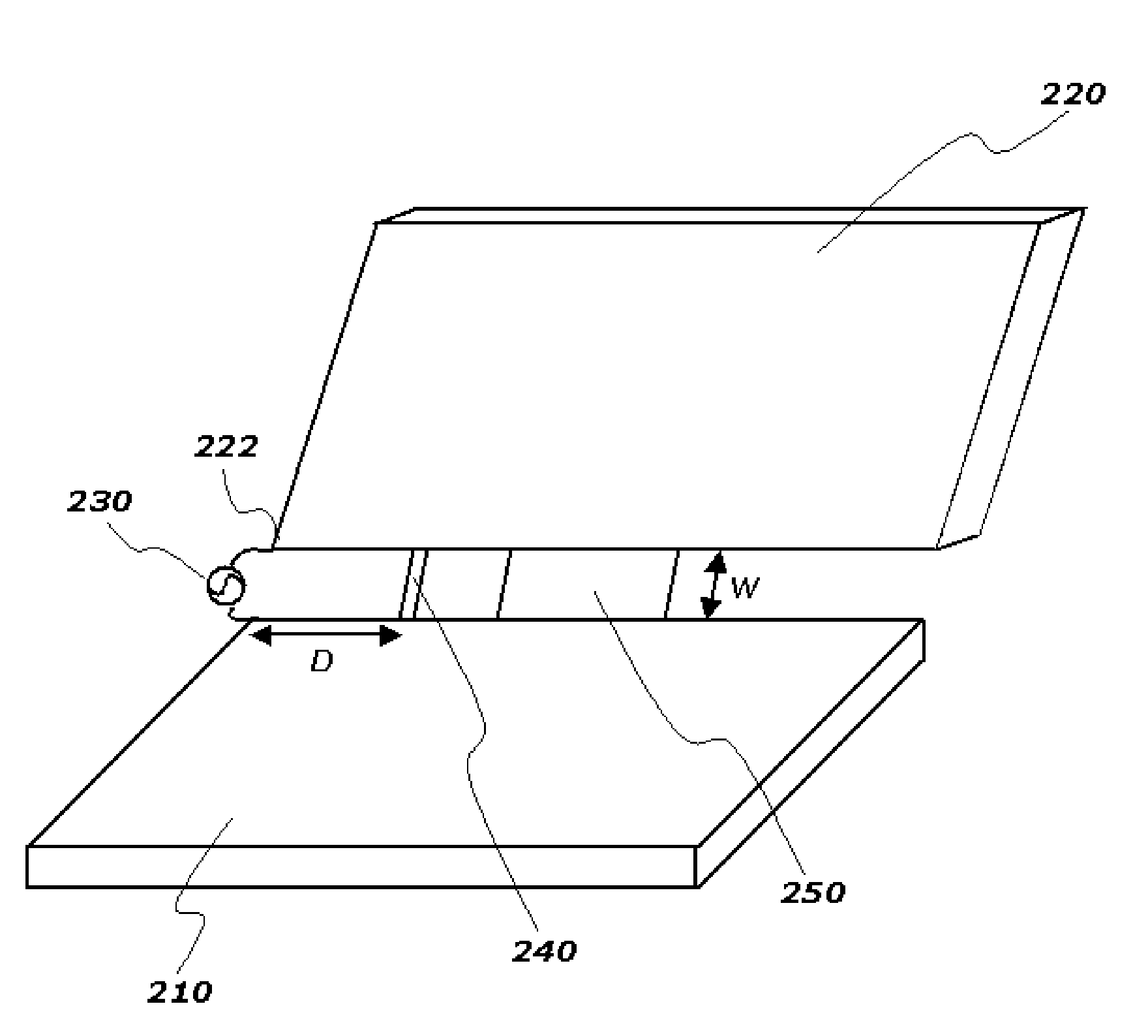
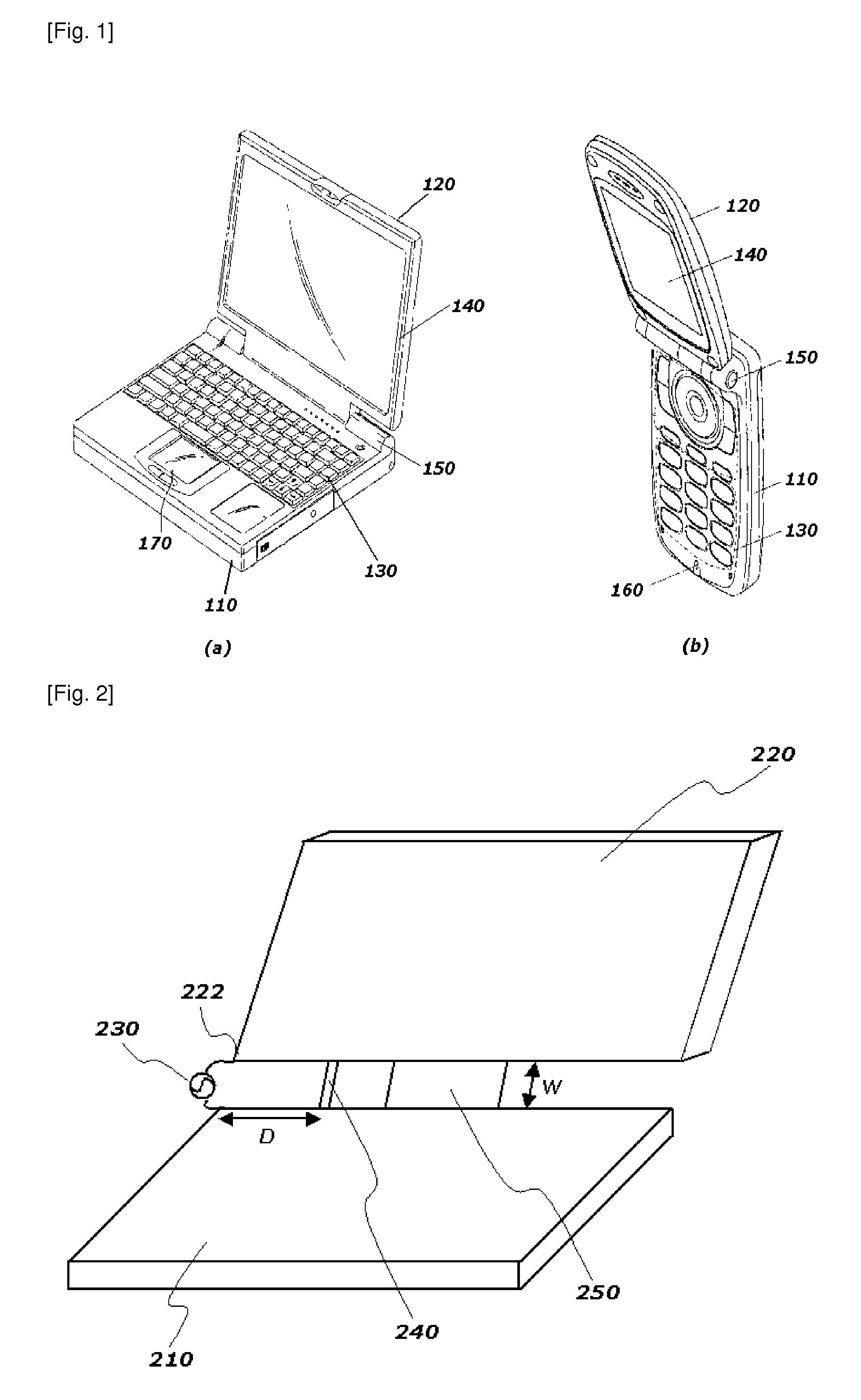
[0030]FIG. 2 illustrates an antenna system according to an embodiment of the present invention. The antenna system includes a first housing 210 and a second housing 220 arranged apart from the first housing 210 by a predetermined distance. The first and second housings 210 and 220 can be made of a conductive material, for example, aluminum.

[0031]The first housing 210 is included in an upper body of an electronic device and a variety of elements such as a CPU, a communication module and a...


PUM


Abstract

An antenna system using a housing of an electronic device and an electronic device having the same are provided. The antenna system includes a first housing of an electronic device, which is formed of a conductive material and connected to a ground plane, and a second housing of the electronic device, which is arranged apart from the first housing by a predetermined distance and formed of a conductive material. A first end of the second housing is connected to a first power supply element. The first housing and the second housing are connected to each other through a first connecting element arranged apart from the first end of the second housing by a pre-determined distance. The antenna system secures a wide radiator to improve antenna efficiency and uses the housings of the electronic device as an antenna without using an additional element to reduce the size of the electronic device.

Description

TECHNICAL FIELD [0001]The present invention relates to an antenna system using a housing of an electronic device and an electronic device having the same, and more particularly, to an antenna system using a housing made of a metal as an antenna radiator and an electronic device having the same.BACKGROUND ART [0002]Electronic devices such as notebook computers, cellular phones, PDA and the like have housings for protecting internal circuits and forming the external appearances thereof. While the shape and structure of a housing depend on the shape of an electronic device employing the housing, a recently widely used electronic device has a folded structure including upper and lower housings connected to each other using a hinge.[0003]A conventional electronic device having the folded structure is described with reference to FIG. 1. FIG. 1(a) is a perspective view of a notebook computer and FIG. 1(b) is a perspective view of a cellular phone. The notebook computer includes an upper bo...

Claims


Application Information

Patent Timeline
Patent Type & Authority Applications(United States)
IPC IPC(8): H01Q1/24
CPCH01Q1/2258H01Q13/08H01Q1/243H01Q1/2266
Inventor RYOU, BYUNG HOONSUNG, WON MOYANG, MYO GEUN
Owner EMW CO LTD
Why Eureka
Try Eureka