Systems and methods for display device backlight compensation

a backlight compensation and display device technology, applied in the field of indirect backlight compensation of liquid crystal display, can solve the problems of increasing increasing the complexity of the electronic display, and increasing the power consumption and the cost to the consumer

Inactive Publication Date: 2010-08-19
CSR TECH INC
View PDF11 Cites 23 Cited by
  • Summary
  • Abstract
  • Description
  • Claims
  • Application Information

AI Technical Summary

Benefits of technology

[0006]The aspects and embodiments of the present invention are directed to systems and methods for illumination of display devices. A compensation mask can be applied to components of a display device, such as a liquid crystal display light valve of a liquid crystal display monitor. This compensation mask can compensate for non-uniformities in light propagation through the display device, and can control characteristics of the light that emits from the display device during operation or use.

Problems solved by technology

As electronic displays become larger and more complex, so too do the lighting sources used to provide the light that emanates from these electronic displays.
Lighting sources for electronic displays add components, cost, and weight to everything from televisions to computer monitors and displays for other electronic devices, increasing power usage and the cost to the consumer, and decreasing efficiency.
Further, the increasing size of some electronic displays for various applications can also affect lighting source component size, cost, and efficiency.

Method used


Image

  • Systems and methods for display device backlight compensation
  • Systems and methods for display device backlight compensation
  • Systems and methods for display device backlight compensation

Examples


Embodiment Construction

[0026]The systems and methods described herein are not limited in their application to the details of construction and the arrangement of components set forth in the description or illustrated in the drawings. The invention is capable of other embodiments and of being practiced or of being carried out in various ways. Also, the phraseology and terminology used herein is for the purpose of description and should not be regarded as limiting. The use of “including”“comprising”“having”“containing”“involving” and variations thereof herein, is meant to encompass the items listed thereafter and equivalents thereof as well as additional items.

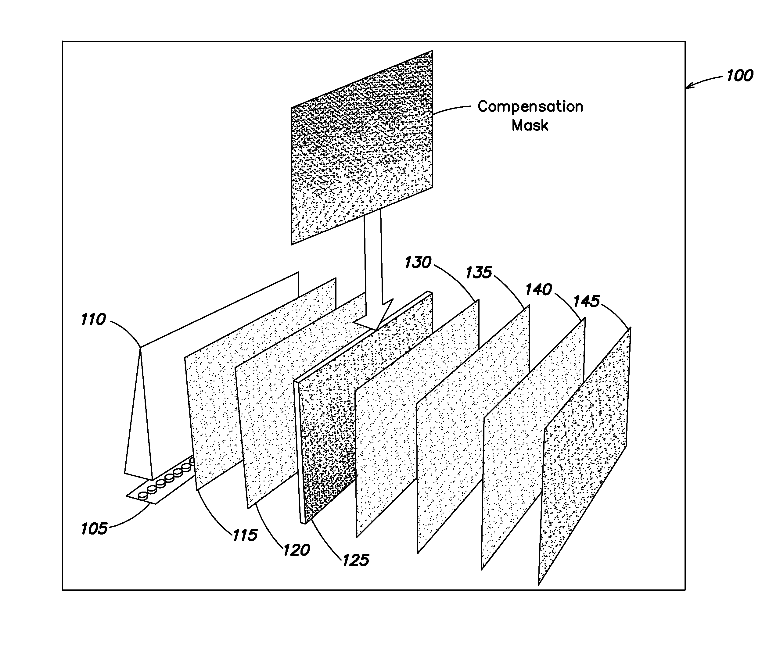
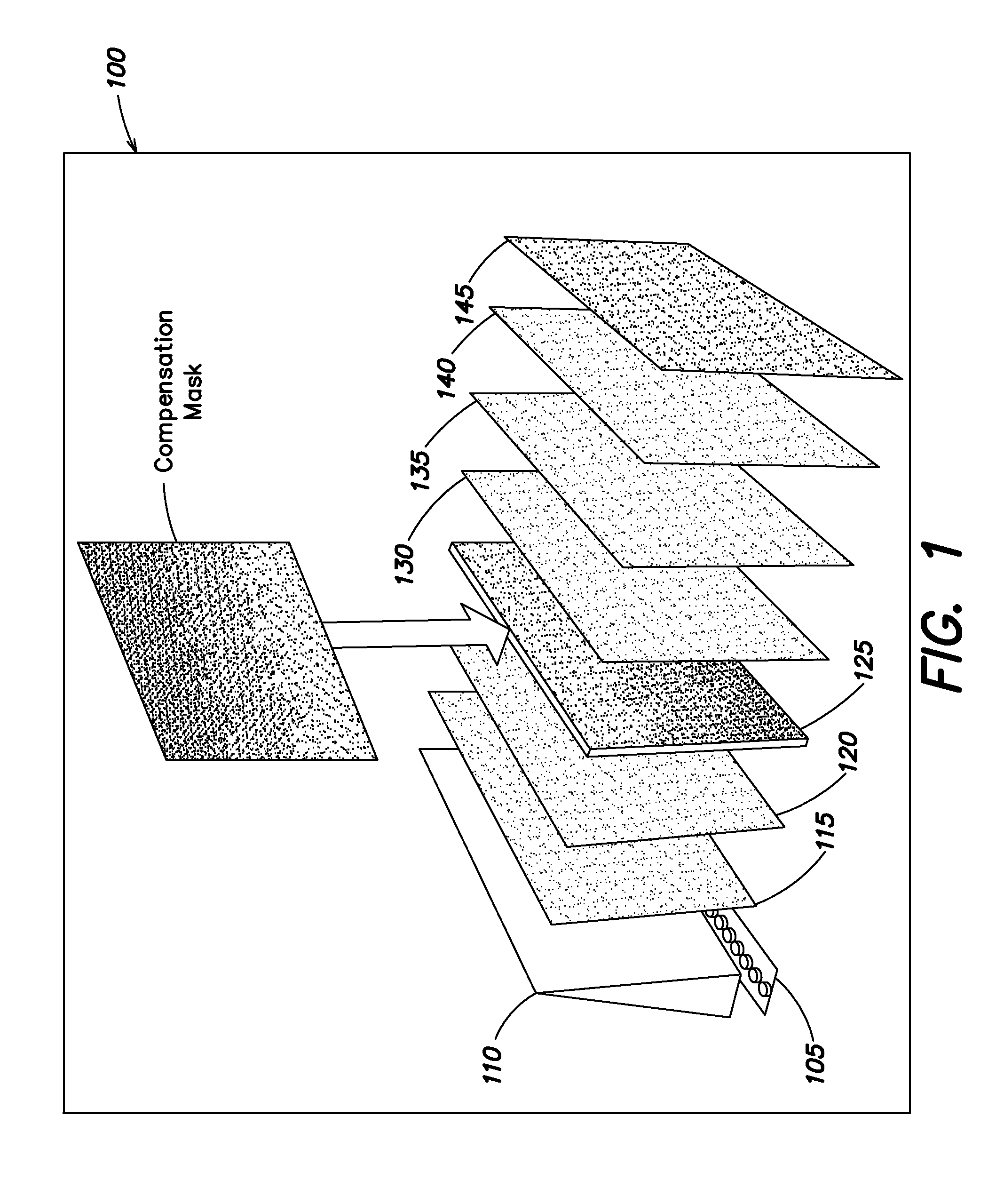
[0027]Various aspects and embodiments are directed to electronic display illumination control, calibration, and compensation. As discussed further below, light from a light source can pass through a light guide and components of a display device, such as polarizers, brightness control films, brightness enhancement films, light valves, and glass panels....


PUM


Abstract

Systems and methods of controlling illumination of a display device are disclosed. These systems and methods can detect a plurality of luminance values in a digital image of the display device that correspond to a plurality of pixel positions of the display device. A first plurality of luminance values of the plurality of luminance values can be mapped to a first pixel position of the plurality of pixel positions of the display device, and a compensation mask value for the first pixel position can be determined based upon the first plurality of luminance values. The compensation mask value can correspond to an adjustment of a luminance value of the first pixel position. The compensation mask value can be provided to a display controller of the display device to permit the display controller to adjust a luminance value of the first pixel position to correspond more closely with luminance values associated with other pixel positions of the plurality of pixel positions of the display device based upon the compensation mask value.

Description

CROSS REFERENCE TO RELATED APPLICATIONS[0001]This application claims priority under 35 U.S.C. 119(e) to U.S. Provisional Application Ser. No. 61 / 153,902 entitled “Backlight Compensation for Wedge Light Guide,” filed Feb. 19, 2009, and to U.S. Provisional Application Ser. No. 61 / 155,996 entitled “Backlight Compensation for Light Guide Plate,” filed Feb. 27, 2009, both of which are incorporated herein by reference in their entirety.BACKGROUND OF THE INVENTION[0002]1. Field of Invention[0003]At least one embodiment of the present invention relates generally to display device illumination and control, and more specifically, to indirect backlight compensation for liquid crystal displays.[0004]2. Discussion of Related Art[0005]Electronic displays such as monitors for computers, televisions, and other electronic devices emanate light that can form images for viewing by a person. Displays of the images vary based on the nature or amount of light emanating from the electronic display. As ele...

Claims


Application Information

Patent Timeline
Patent Type & Authority Applications(United States)
IPC IPC(8): G09G3/36H01J9/42
CPCG09G3/3611G09G2320/0233G09G2360/147G09G2320/0295G09G2320/0285
Inventor AULD, DAVID
Owner CSR TECH INC
Why Eureka
Try Eureka