Fuel feed apparatus having sub tank and jet pump

a technology of fuel feed apparatus and jet pump, which is applied in the direction of charge feed system, machine/engine, thin material processing, etc., can solve the problems of reducing the amount of return fuel exhausted from the pressure regulator, the inability of the fuel pump to draw fuel in the tank section, and the decrease of the amount of discharged fuel into the sub-tank. , to achieve the effect of stable control characteristic and simplified structure of the pressure regulator

Active Publication Date: 2006-02-02
AISAN IND CO LTD
View PDF22 Cites 25 Cited by
  • Summary
  • Abstract
  • Description
  • Claims
  • Application Information

AI Technical Summary

Benefits of technology

[0013] In view of the foregoing problems, it is a first object of the present invention to provide a fuel feed apparatus, in which multiple jet pump supply fuel from multiple tank sections, so that fuel can be secured in the sub-tank. The second object of the present invention is to provide a fuel feed apparatus, in which variation of the amount of fuel received in the sub-tank can be decreased, regardless of the amount of fuel supplied from the sub-tank. The third object of the present invention is to provide a fuel feed apparatus having a small pressure regulator. The pressure regulator has a simple structure, and is capable to stably control fuel pressure.
[0017] Specifically, the first jet pump and the second jet pump are connected with a vent hole of the fuel pump. An amount of fuel supplied from the vent hole to the jet pumps is substantially constant, regardless of a fuel consumption amount in an engine side. Accordingly, substantially constant fuel amount can be secured in the sub-tank regardless of a fuel consumption amount in the engine side. Therefore, fuel shortage in the sub-tank can be prevented. Besides, overflowing a large amount of fuel from the sub-tank into the fuel tank and the first-tank section can be also prevented.
[0019] In this case, fuel is supplied to the jet pump from the upstream side of the valve port of the pressure regulator. Therefore, variation of a pressure control characteristic of the pressure regulator does not be largely affected by the jet pump, in this structure. Therefore, the structure of the pressure regulator can be simplified, while securing stable control characteristic of the pressure regulator.

Problems solved by technology

Besides, if fuel is decreased in the tank section where the fuel pump is received, the fuel pump cannot draw fuel in the tank section.
However, if the jet pump is installed outside of the sub-tank, fuel is discharged from outside of the sub-tank, and the discharged fuel may not be supplied into the sub-tank when the vehicle is inclined, for example.
However, in this case, when an amount of pressure-controlled fuel discharged from the pressure regulator is increased, an amount of the return fuel exhausted from the pressure regulator decreases.
As a result, an amount of fuel received in the sub-tank decreases, and the fuel pump may not properly draw fuel received in the sub-tank.
As a result, a large amount of fuel may overflow from the sub-tank, and the overflowing fuel may agitate fuel received in the fuel tank.
Besides, noise may be generated when fuel overflowing from the sub-tank drops onto the inner wall of the fuel tank.
However, in this case, an amount of fuel consumed in the engine varies due to a change of an operation condition.
However, if the diaphragm is used in the pressure regulator, the structure of the pressure regulator becomes complicated.
Accordingly, it becomes difficult to downsize the pressure regulator, if the diaphragm is used in the pressure regulator.

Method used


Image

  • Fuel feed apparatus having sub tank and jet pump
  • Fuel feed apparatus having sub tank and jet pump
  • Fuel feed apparatus having sub tank and jet pump

Examples


first embodiment

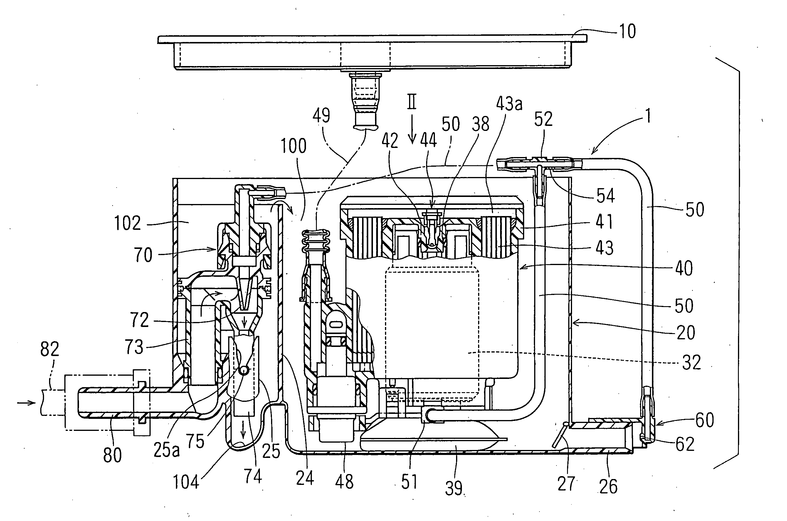
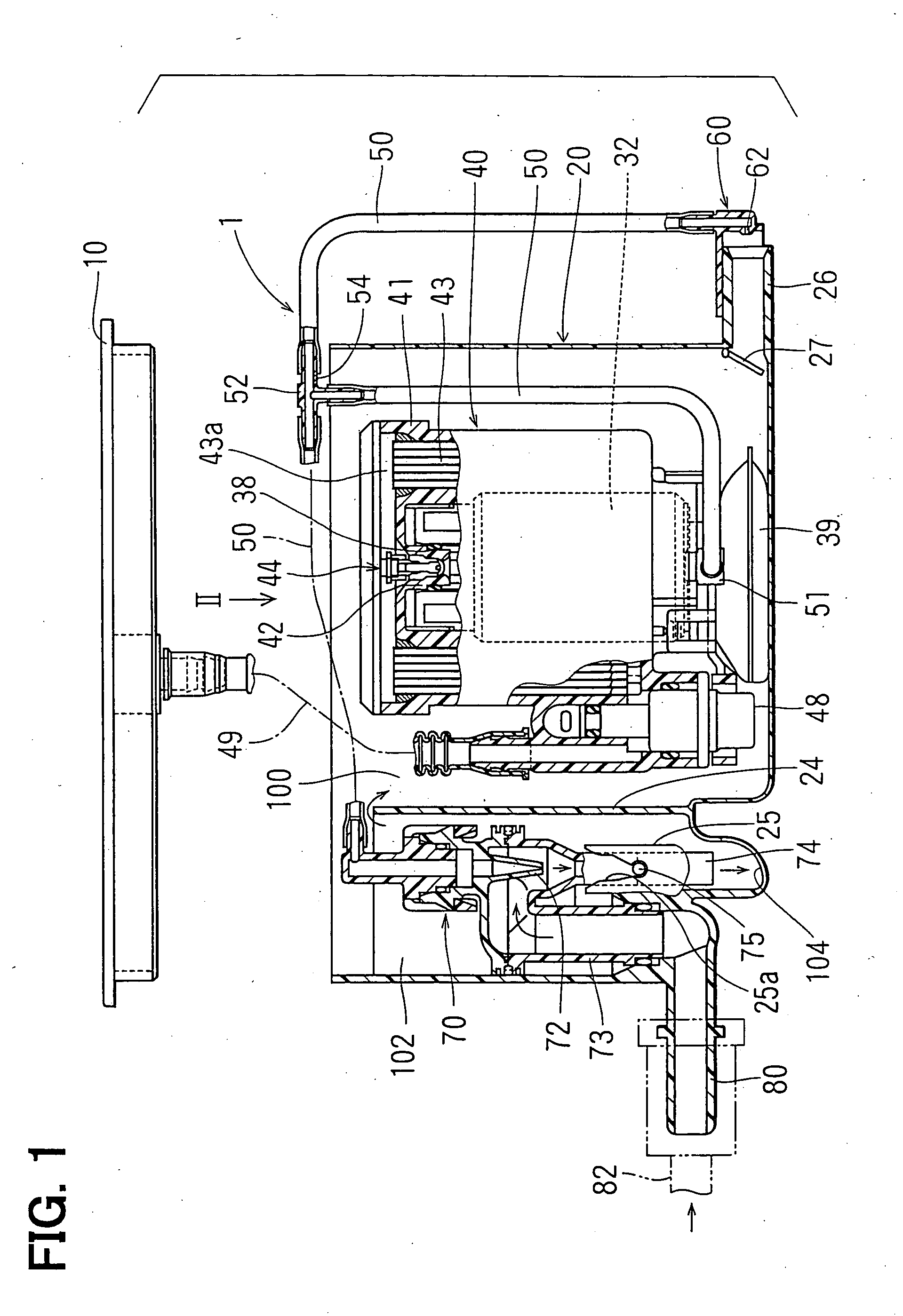
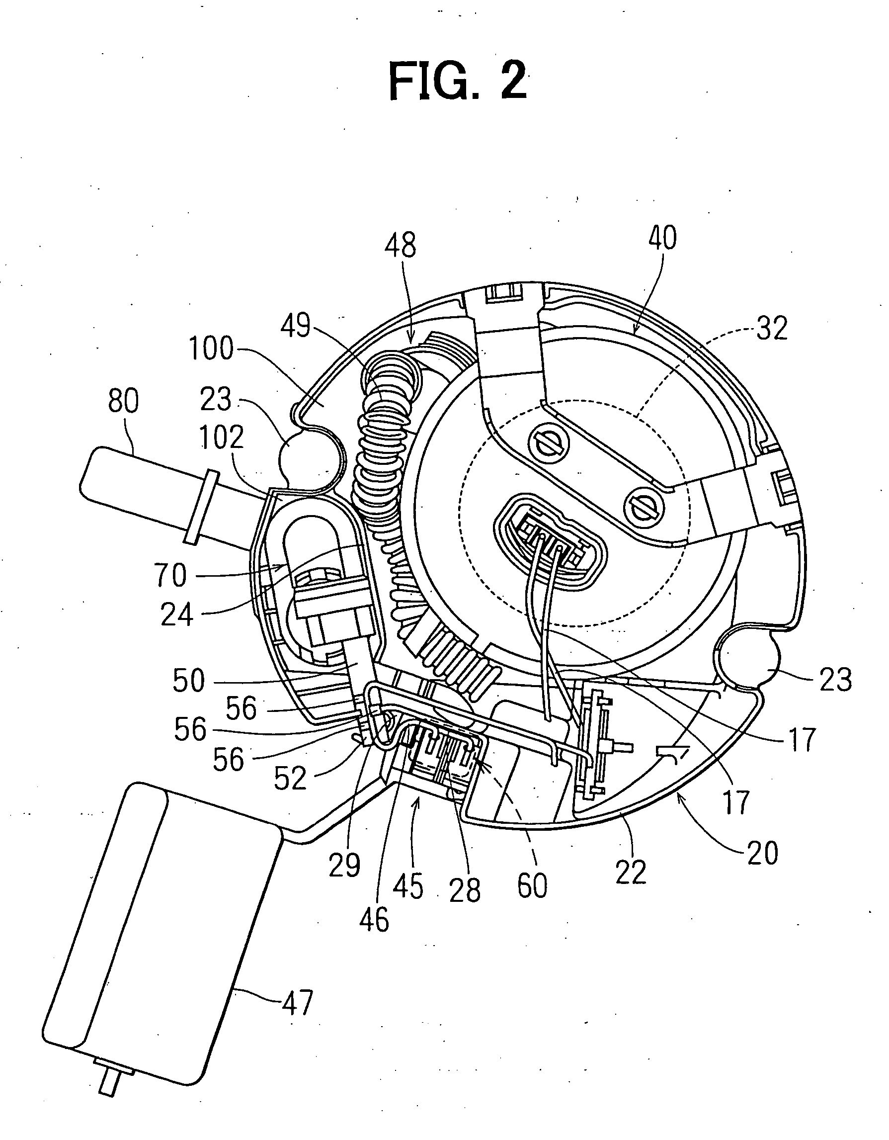
[0031] As shown in FIGS. 1 and 2, a fuel feed apparatus 1 is received in a fuel tank 2 for transferring fuel in the fuel tank 2 to an exterior device, such as engine, provided outside of the fuel tank 2. The fuel feed apparatus 1 includes a flange 10, a sub-tank 20, a pump module 40, a jet pump 60 (first jet pump), a jet pump 70 (second jet pump) and the like. FIG. 1 shows a cross-sectional view taken along a polygonal line passing the jet pump 60, a pressure regulator 48 and the jet pump 70 in FIG. 2. Here, the jet pump 60 is located under a sender gauge 45, and is not shown in FIG. 2. Therefore, the cross-sectional view shown in FIG. 1 is wider than a cross-sectional view taken along a straight line. The flange 10 is formed in a disc-shape and used as a lid in the fuel feed apparatus 1.

[0032] Referring back to FIG. 1, the pump module 40 includes a filter case 41 and a filter element (fuel filter) 43. The filter case 41 surrounds the outer periphery of the fuel pump 32. The filter...

second embodiment

[0073] As shown in FIG. 6, fuel is pressurized in the fuel pump 32 and discharged from the vent hole 202 of the fuel pump 32. The vent hole 202 is connected with the jet pump 60 through a first pipe 326. The first pipe 326 is equivalent to the nylon pipe 50 in the first embodiment.

[0074] As shown in FIG. 7, the fuel pump 32 has a housing 350. The housing 350 receives a discharge-side cover 346, an armature 368, four magnets 370, a casing 366, suction-side cover 362 and the like. Each magnet 370 is shaped in an arc-shape in its cross-section. The four arc-shaped magnets 370 are arranged in the inside peripheral wall of the housing 350 in a predetermined interval, so that different magnetic poles are alternatively formed in the circumferential direction of the housing 350.

[0075] The armature 368 is rotatably received in the housing 350 with the shaft 37. A commutator 348 is provided on the one end of the armature 368. The shaft 37 is press-inserted into a core 352. Multiple bobbins ...

third embodiment

[0092] As shown in FIG. 9, fuel is drawn from the second pipe 312, and supplied into the jet pump 60 in this embodiment.

[0093] Specifically, a fourth pipe 376 is connected with the second pipe 312 for introducing fuel discharged from the discharge port 40a of the pump module 40 into the jet pump 60. Fuel is pressurized in the fuel pump 32 by rotation of the impeller 34, and flows into the second pipe 312 through the filter element 43. Fuel flowing in the second pipe 312 is partially introduced into the jet pump 60 through the fourth pipe 376. The fuel introduced into the jet pump 60 is jetted from the nozzle 62 into the sub-tank 20. The amount of fuel introduced into the jet pump 60 corresponds to the flow passage area of the nozzle 62 of the jet pump 60.

[0094] Fuel is introduced from the upstream side of the valve port 342 of the pressure regulator 48 into the jet pump 60. Accordingly, pressure in the downstream side of the pressure regulator 48 is not affected by the jet pump 60...


PUM


Abstract

A fuel feed apparatus including a sub-tank is received in a fuel tank having multiple tank sections. Multiple jet pumps respectively transfers fuel received in the tank sections into the sub-tank. Therefore, even if a fuel amount received in a single tank section decreases, fuel can be steadily supplied from another tank section. Intermediately pressurized fuel in a fuel pump is supplied to the jet pumps, so that fuel can be steadily supplied to the jet pumps regardless of fuel consumption amount in an engine. Fuel is drawn from an upstream side of a pressure regulator, and supplied to the jet pump. The pressure regulator has an urging unit, and controls fuel pressure without using a diaphragm. Therefore, the pressure regulator is simplified and downsized.

Description

CROSS REFERENCE TO RELATED APPLICATIONS [0001] This application is a division of application Ser. No. 10 / 793,039 filed Mar. 5, 2004 which is based on Japanese Patent Application No. 2003-90908 filed on Mar. 28, 2003, No. 2003-112660 filed on Apr. 17, 2003 and No. 2003-68320 filed on Mar. 13, 2003, the disclosures of all of the above applications are incorporated herein by reference.BACKGROUND OF THE INVENTION [0002] 1. Field of the Invention [0003] The present invention is related to a fuel feed apparatus that transfers fuel received in a fuel tank having multiple inner tank sections into a sub-tank received in the fuel tank, and supplies the fuel received in the sub-tank to an internal combustion engine. [0004] 2. Description of Related Art [0005] A fuel feed apparatus including a fuel pump is provided in a fuel tank having multiple tank sections in a related art (e.g., JP-A-5-2830). In this case, fuel is jetted from the fuel pump into a tank section where the fuel pump is received...

Claims


Application Information

Patent Timeline
Patent Type & Authority Applications(United States)
IPC IPC(8): F02M37/00F02M37/02F02M37/10
CPCF02M37/106F02M37/025Y10T137/86187
Inventor NAGATA, KIYOSHI
Owner AISAN IND CO LTD
Why Eureka
Try Eureka