
Torque measuring apparatus and actuator drive control system

a technology of torque measurement and actuator, which is applied in the direction of instruments, apparatus for force/torque/work measurement, and tensile measurement, etc., can solve the problems of loss of reproducibility of hysteresis, difficult to perform accurate force (torque) control to the object, and inability to detect high frequency signals

Inactive Publication Date: 2012-04-24
SONY CORP
View PDF12 Cites 22 Cited by
  • Summary
  • Abstract
  • Description
  • Claims
  • Application Information

AI Technical Summary

Benefits of technology

The present invention provides an excellent torque measuring apparatus and an actuator drive control system. The apparatus includes a flexure element attached between the output shaft of an actuator or a speed reducer and a load object, with strain gauges bonded to the main flexure part of the flexure element. The strain gauges are positioned to measure the torque generated by the flexure element in response to the applied torque. The apparatus is designed to suppress the generation of strain in a direction other than the expected direction, and the torque can be measured accurately based on the output signals of the strain gauges. The actuator drive control system is designed to control the actuator in real-time, ensuring accurate torque measurement and optimal performance.

Problems solved by technology

For example, even if an impulse force is exerted on the load side, it is merely transmitted as the repulsive force to the sensor through the electromagnetic system, a signal of high frequency cannot be detected.
However, since not only the characteristic of a load, but also the characteristics of a halfway transmission system, a speed reducer and the like are also included, it is difficult to perform accurate force (torque) control to the object.
Although the nonlinearlity is not fatal, the dead zone causes a minute component to be unable to be detected, the reproducibility of the hysteresis is lost, and the accuracy is impaired.

Method used


Image

  • Torque measuring apparatus and actuator drive control system
  • Torque measuring apparatus and actuator drive control system
  • Torque measuring apparatus and actuator drive control system

Examples


Embodiment Construction

[0060]Hereinafter, an embodiment of the invention will be described in detail with reference to the drawings.

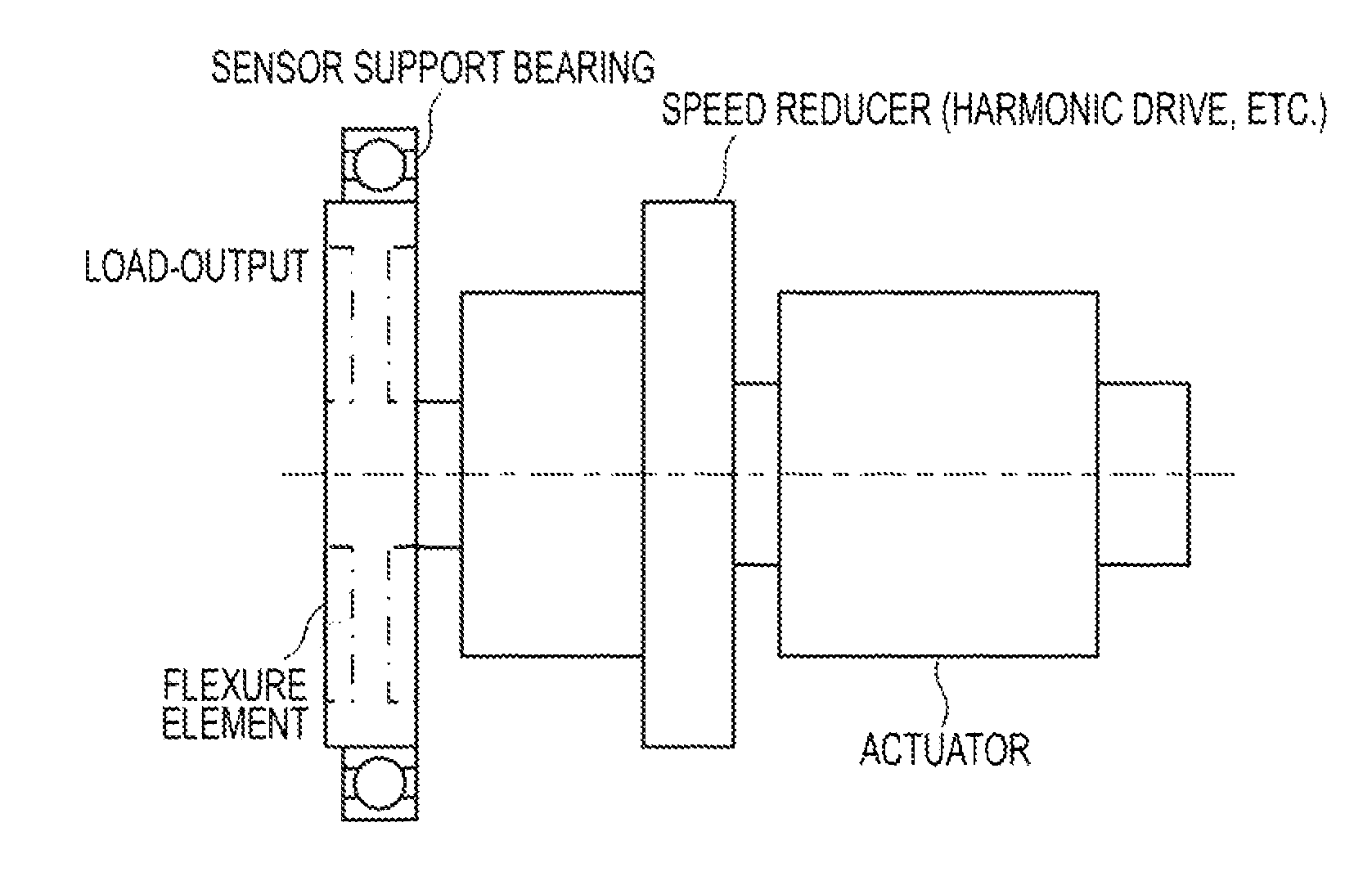
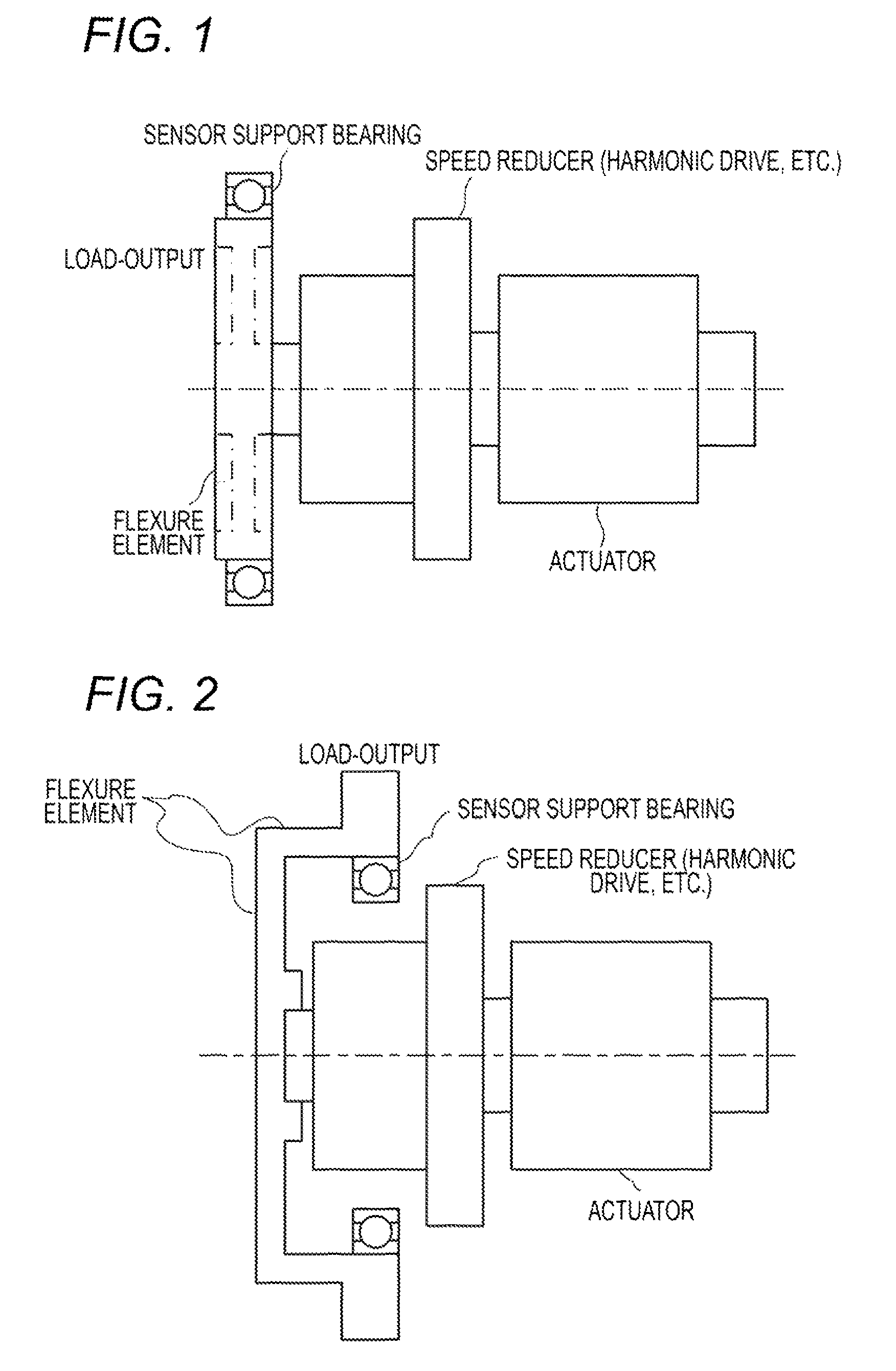
[0061]FIG. 1 schematically shows a structure of a drive control system including an actuator to which an embodiment of the invention can be applied and peripheral devices attendant on this. The illustrated drive control system is roughly divided into three modules of an actuator including a motor and the like, a speed reducer and a torque sensor, and can be called “actuator unit with speed reducer having torque measurement function”. That is, the drive control system can measure torque applied to the output shaft of the actuator unit having the speed reducer, and can perform torque control of the actuator.

[0062]As is well known in this industry, an actuator and a speed reducer include various elements, such as hysteresis, friction, and nonlinearity, which cause model identification to become difficult. As described later in detail, the torque sensor used in the embodiment is ...


PUM

PropertyMeasurementUnit
torque measuringaaaaaaaaaa
torqueaaaaaaaaaa
circumferenceaaaaaaaaaa

Abstract

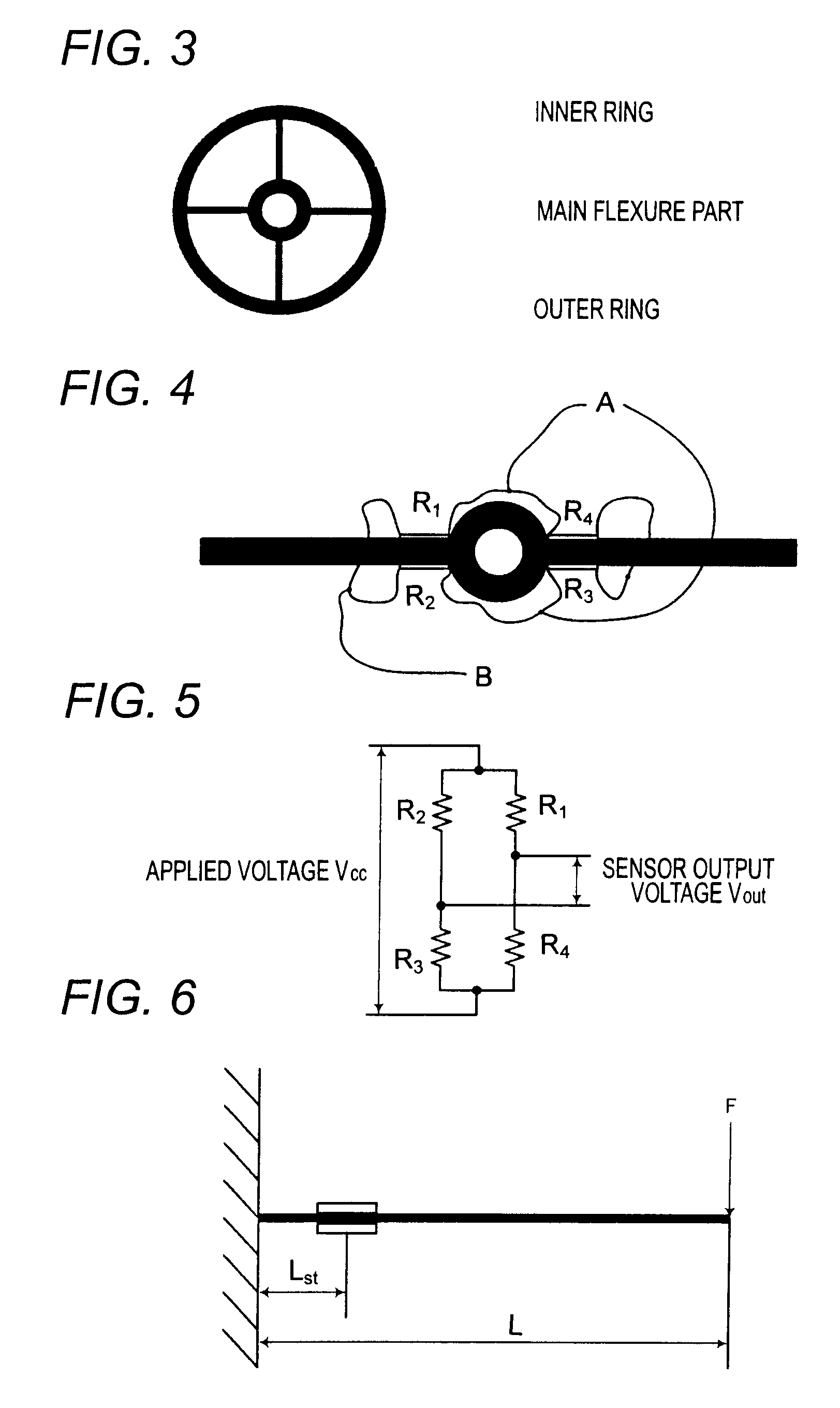
A torque measuring apparatus includes: a flexure element that is attached between an output shaft of an actuator or a speed reducer as a torque measurement object and a load object, and includes a main flexure part displaced mainly around the output shaft according to a torque applied from the load object, and an auxiliary flexure part to remove a displacement component other than the displacement of the main flexure part around the output shaft; and at least one pair of strain gauges attached to the main flexure part. The torque is measured based on electric signals outputted from the respective strain gauges.

Description

BACKGROUND OF THE INVENTION[0001]1. Field of the Invention[0002]The present invention relates to a torque measuring apparatus attached to an output shaft of, for example, an actuator motor and to measure a torque applied to the output shaft and an actuator drive control system, and particularly to a torque measuring apparatus in which strain gauges are bonded to a flexure element to generate strain by the application of torque and the torque is measured based on output signals of the strain gauges, and an actuator drive control system.[0003]2. Description of the Related Art[0004]A torque sensor is studied and developed from long ago. The torque sensor is used for a drive system of, for example, an actuator control apparatus of force control system, or “haptic device” for providing the sense of force or the sense of touch to the operator in addition to visual information and aural information. Here, the force control is a control method in which a target value of force to be applied ...

Claims


Application Information

Patent Timeline
Patent Type & Authority Patents(United States)
IPC IPC(8): G01L1/22
CPCG01L3/1457
Inventor KATO, KEISUKENAGASAKA, KENICHIRO
Owner SONY CORP
Learn More