Transmitter circuits and apparatus of wireless application

a transmitter circuit and wireless application technology, applied in the direction of amplification control details, supply voltage varying control, transmission, etc., can solve the problems of current consumption increasing and the problem of solving the problem, and achieve the effect of reducing the current consumption required to deliver the moderate or small power outpu

Inactive Publication Date: 2007-12-06
RENESAS ELECTRONICS CORP
View PDF2 Cites 23 Cited by
  • Summary
  • Abstract
  • Description
  • Claims
  • Application Information

AI Technical Summary

Benefits of technology

[0008]However, a problem to be solved underlies each of the two foregoing related arts. In the former polar-loop transmitter circuit, two feedback circuits for use in controlling an amplitude or a phase are active during transmission. This poses a problem in that current consumption increases especially when output power is small. On the other hand, in the latter polar-loop low-power type in which the amplitude is controlled in an open loop and the phase alone is controlled in a closed loop, since the power amplifier or power amplifier module (hereinafter, simply, a power amplifier) is controlled in the open loop, the circuit scale may be small. This is helpful in lowering power consumption.
[0010]One of the objects of the present invention is to provide a transmitter circuit in which the control characteristic of a power amplifier can be properly sustained irrespective of a use environment, and which requires little current consumption.
[0012]According to the present invention, when the power amplifier delivers a large power output exhibiting strong nonlinearity, a transmitter circuit in which two feedback circuits to be used to control an amplitude and a phase respectively are active is started. When the power amplifier delivers a moderate or small power output, the amplitude is controlled in an open loop. Thus, the control characteristic of the power amplifier is properly sustained irrespective of a use environment. Moreover, current consumption required to deliver the moderate or small power output can be reduced.

Problems solved by technology

However, a problem to be solved underlies each of the two foregoing related arts.
This poses a problem in that current consumption increases especially when output power is small.

Method used


Image

  • Transmitter circuits and apparatus of wireless application
  • Transmitter circuits and apparatus of wireless application
  • Transmitter circuits and apparatus of wireless application

Examples


first embodiment

[0036]To begin with, a transmitter circuit in accordance with the first embodiment of the present invention will be described in conjunction with FIG. 1 to FIG. 9.

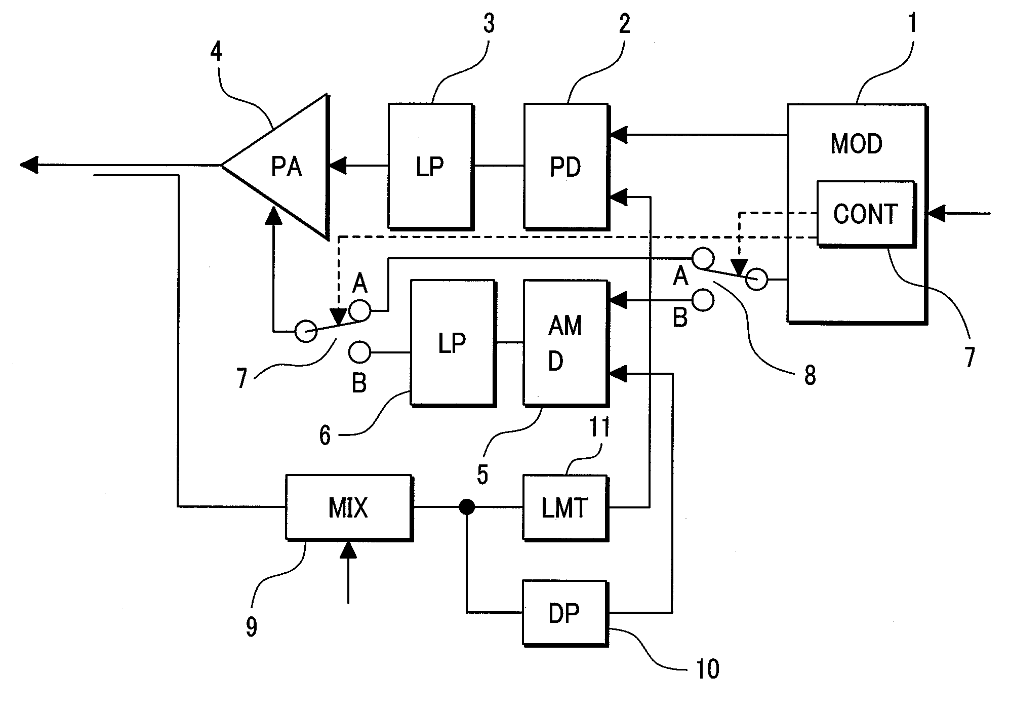
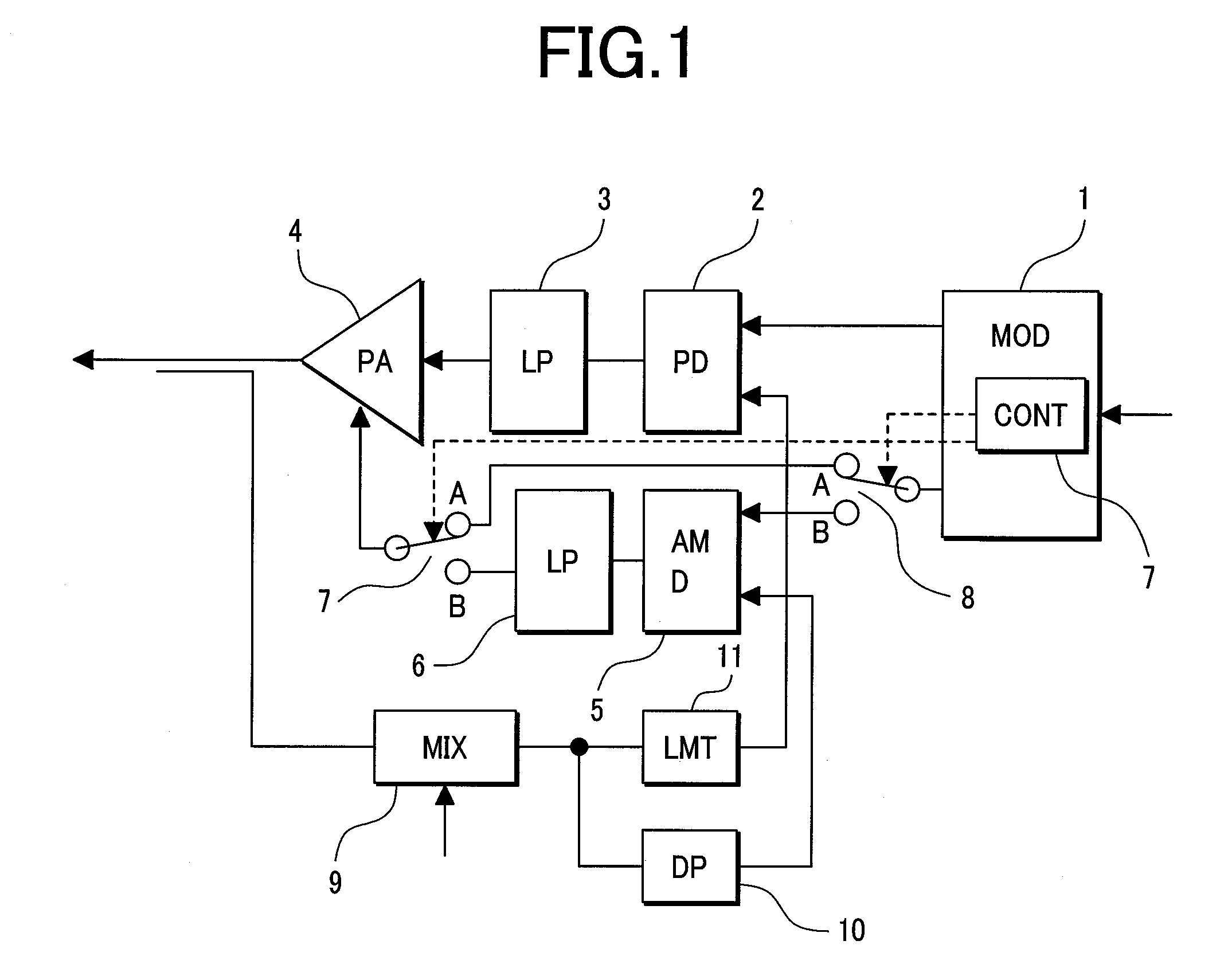
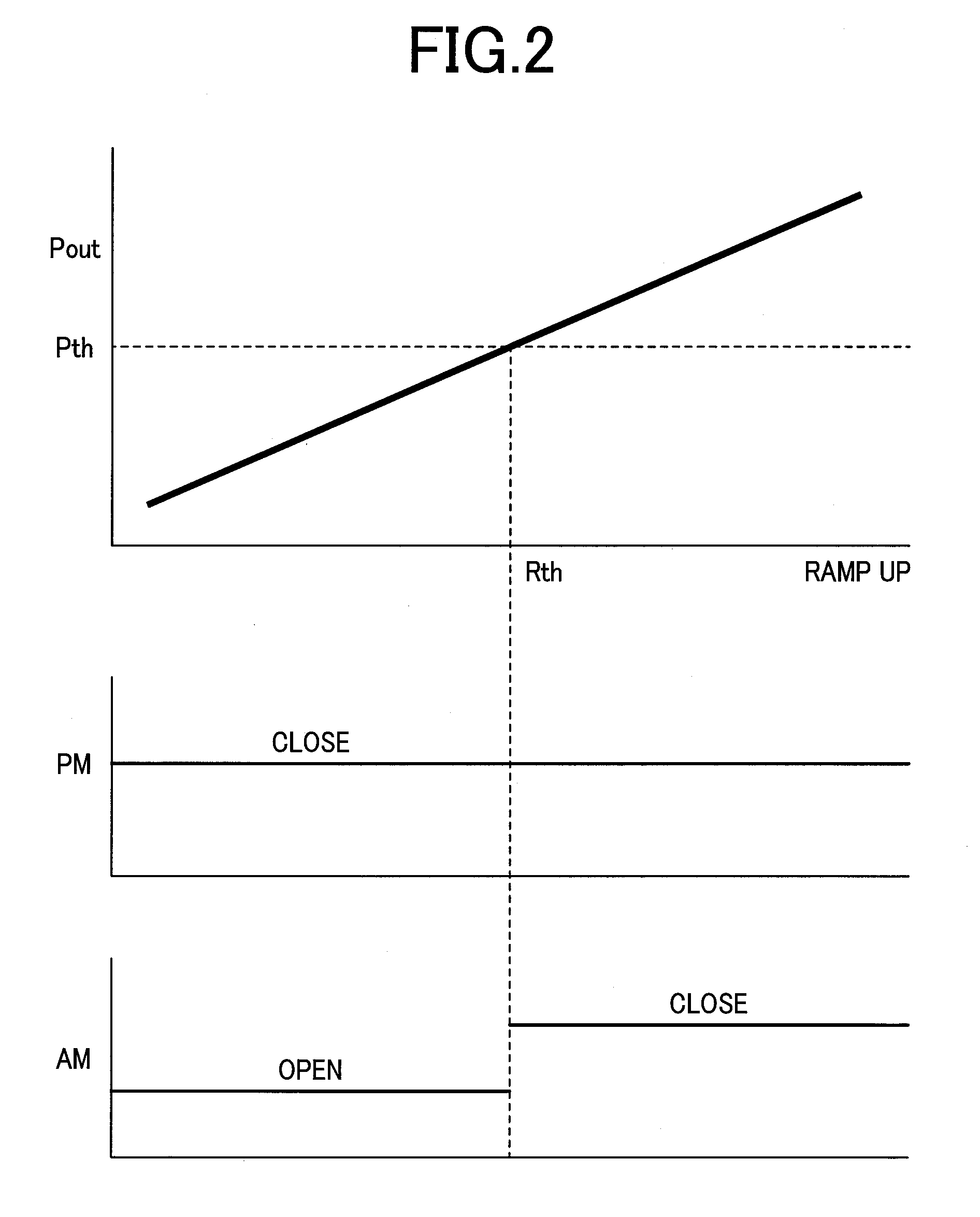
[0037]First, the fundamental configuration of the first embodiment will be described in conjunction with FIG. 1 and FIG. 2. FIG. 1 shows a transmitter circuit in accordance with the first embodiment of the present invention. FIG. 2 is an explanatory diagram concerning the operation of the transmitter circuit shown in FIG. 1.

[0038]The transmitter circuit shown in FIG. 1 is employed in an apparatus for wireless applications that is suitable for the EDGE which is a broadband transmission facility evolved from the GSM. Reference numeral 1 denotes a modulator. The modulator 1 receives transmittal information (a ramp signal or transmittal data) from a baseband circuit (not shown), and produces and transmits a transmittal signal or a phase- or amplitude-modulated signal. A phase-modulated (PM) signal produced by the modulator 1 i...

second embodiment

[0057]Referring to FIG. 10 to FIG. 15, the second embodiment of the present invention will be described below. FIG. 10 shows the major portion of a transmitter circuit in accordance with the second embodiment of the present invention. FIG. 11 shows an operating timing signal generation circuit employed in the second embodiment. FIG. 12 is an explanatory diagram concerning the operation of the second embodiment.

[0058]In FIG. 10, there are shown a modulator 1, a phase detector 46, a loop filter 3 composed of a transmittal oscillator and a filter 48, a power amplifier 4, and an antenna switch 61. The power amplifier 4 includes a heterojunction bipolar transistors (HBTs) connected in multiple stages, a bias circuit 28, a coupler 49, a wave detection circuit 50, and an error amplifier 51. Moreover, components constituting a phase locked loop or an amplitude loop include an amplitude comparator 47, a variable amplifier 52, a stepping gain control amplifier 53, a variable amplifier 54, a l...

third embodiment

[0080]FIG. 16 and FIG. 17 show the third embodiment of the present invention. FIG. 16 shows a transmitter circuit in accordance with the third embodiment of the present invention. FIG. 17 shows the operating timings of the present embodiment. In the present embodiment, unlike the first embodiment, a buffer amplifier 400 is interposed between the loop filter 3 and power amplifier 4 while being included in a radiofrequency IC. A bypass switch 410 is connected in parallel with the buffer amplifier 400. A feedback control signal is fetched from the output terminal of the buffer amplifier 400 within the radiofrequency IC. A selection switch 420 through which the routing of the output of the mixer 9 to the control input terminal of the power amplifier 4 and the routing thereof to the input terminal of the buffer amplifier 400 are switched is included in the radiofrequency IC. The switching control circuit 700 transmits a control signal with which the connections through the selection swit...


PUM


Abstract

In conventional polar-loop transmitter circuits, using two feedback circuits intended to control the amplitude in an open loop and phase of a power output in closed loop, respectively, during transmission, causes current consumption to increase during delivery of a small power output. Therefore, a complex table has to be prepared in order to correct the nonlinearities in the amplitude-to-amplitude characteristic of the power amplifier and the amplitude-to-phase characteristic thereof. In order to reduce the current consumption required for the delivery of a moderate or small power output, a polar-loop transmitter circuit in which two feedback circuits intended to control the amplitude and phase of the power output respectively are active when the power amplifier delivers a large power output exhibiting strong nonlinearity, and when the power amplifier delivers a moderate or small power output, the amplitude of the power output is controlled in the open loop.

Description

CLAIM OF PRIORITY[0001]The present application claims priority from Japanese application JP 2006-151762 filed on May 31, 2006, the content of which is hereby incorporated by reference into this application.FIELD OF THE INVENTION[0002]The present invention relates to transmitter circuits and an apparatus for a wireless application using the transmitter circuits. More particularly, the present invention is concerned with a transmitter circuit for mobile communications or for portable cellular phones, or a transmitter circuit suitable for the Enhanced Data GSM Environment (EDGE) that is a broadband transmission facility evolved from the Global System for Mobile Communications (GSM) which is the cellular phone system prevalent throughout Europe, and an apparatus for wireless applications using the transmitter circuits.BACKGROUND OF THE INVENTION[0003]Existing polar-loop transmitter circuits include a type of transmitter circuit in which: a signal transferred from a signal source is defi...

Claims


Application Information

Patent Timeline
Patent Type & Authority Applications(United States)
IPC IPC(8): H04B7/00
CPCH03G3/004H03G1/0088
Inventor TANAKA, SATOSHIAKAMINE, YUKINORI
Owner RENESAS ELECTRONICS CORP
Why Eureka
Try Eureka