Maskless exposure method

Active Publication Date: 2010-08-19
LG ELECTRONICS INC
View PDF15 Cites 35 Cited by
  • Summary
  • Abstract
  • Description
  • Claims
  • Application Information

AI Technical Summary

Benefits of technology

[0022]According to the present disclosure, there is an advantage in that it is possible to perform a more precise optical alignment using the first pattern of the maskless exposure part and the second pattern of the MRU.
[0023]There is another advantage in that the aligning camera is provided capable of aligning optical centers of the DMD, MAL and MRU.

Problems solved by technology

However, there is a problem in that a precise exposure process cannot be performed due to generation of a light intensity deviation between the lighting devices.

Method used


Image

  • Maskless exposure method
  • Maskless exposure method
  • Maskless exposure method

Examples


Embodiment Construction

[0072]Now, exemplary implementations of the present inventive disclosure will be described in detail with reference to the accompanying drawings.

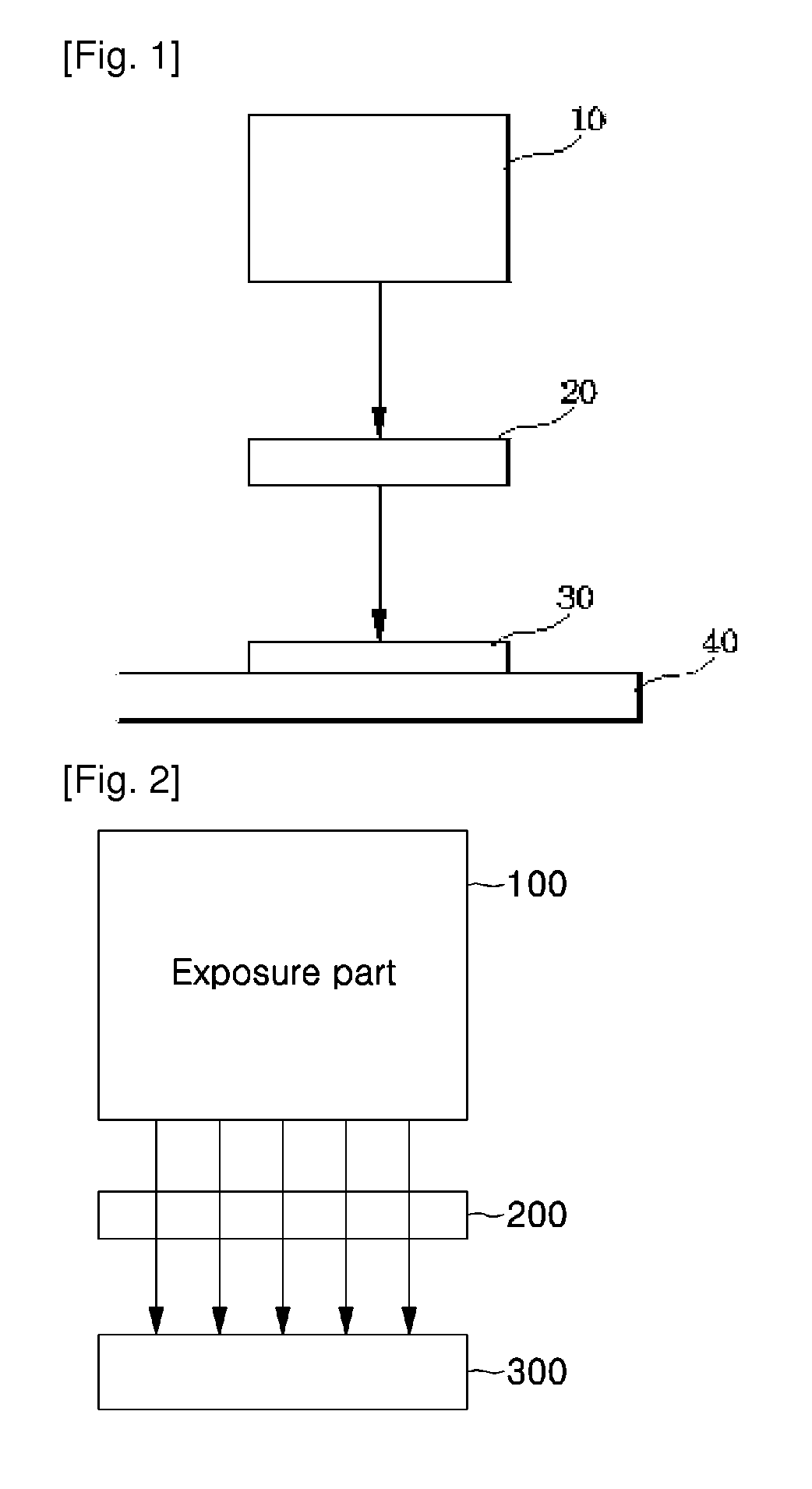
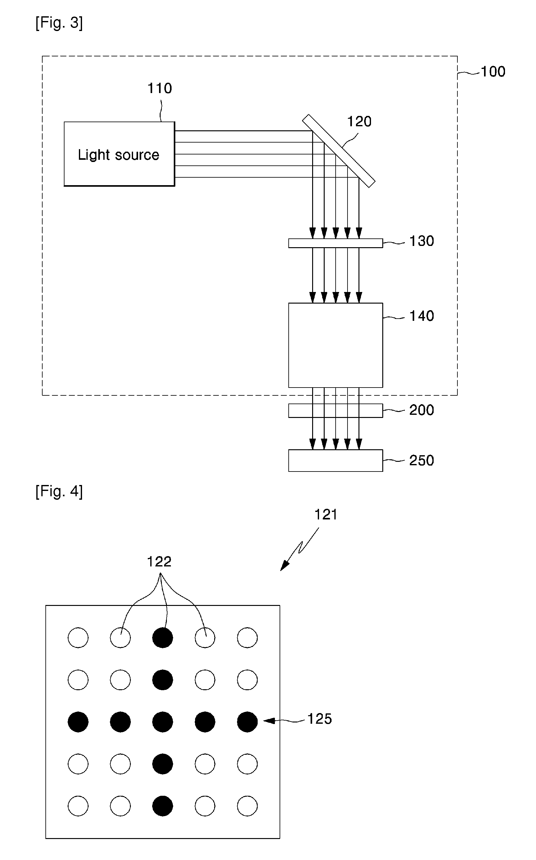
[0073]FIG. 2 is a schematic structural view illustrating a maskless exposure apparatus according to a first implementation of the present disclosure. The maskless exposure apparatus includes a maskless exposure part 100 for exposing a predetermined object with a light having a first pattern; a Master Reference Unit (MRU) 200 formed of a light transmissive material and formed with a second pattern that does not transmits the light having the first pattern; and a MRU camera 250 for photographing the light transmitted through the MRU 200.

[0074]Therefore, the maskless exposure apparatus of the present disclosure can perform optical alignment more precisely using the first pattern of the maskless exposure part 100 and the second pattern of the MRU 200.

[0075]Herein, the MRU 200 is a component for referring to an absolute reference of the maskless...


PUM


Abstract

Disclosed is a maskless exposure method, where it is possible to perform a more precise optical alignment using a first pattern of a maskless exposure part and a second pattern of a main reference unit, and it is also possible to reduce generation of a blur in an exposed pattern.

Description

TECHNICAL FIELD[0001]The following description relates generally to a maskless exposure method.BACKGROUND ART[0002]Recently, with rapid development of an information society, a need for a flat panel display (FPD) having excellent properties such as slim thickness, light weight and low power consumption has been raised.[0003]To meet this need, there has been developed image display panels such as a Liquid Crystal Display (LCD), a Plasma Display Panel (PDP), an Electroluminescent Display (ELD) and a Vacuum Fluorescent Display (VFD).[0004]Among these panels, the LCD panel has been actively used for a notebook computer or a desktop monitor owing to its excellent resolution, color displaying ability and image quality.[0005]Meanwhile, as the panels are enlarged according to customer demands, various processing facilities have been developed and facilities using new technologies have been developed.[0006]In particular, an exposure apparatus is essential for forming patterns in each display...

Claims


Application Information

Patent Timeline
IPC IPC(8): G03B27/32
CPCG03F7/70275G03F9/7088G03F9/7015G03F7/70291
Inventor SHIN, YOUNG HOONSEO, WON HOPARK, MYUNG JULEE, HYUNG JINCHA, SANG HWANLEE, TAE HORHEE, CHANG JU
Owner LG ELECTRONICS INC
Why Eureka
Try Eureka