

Method and system for a single frame camera module active alignment tilt correction
a single-frame camera and active alignment technology, applied in the field of camera module components, can solve the problems of low throughput of conventional active alignment methods, degrade the image quality of finished cameras, and difficult and expensive to meet mass production demands, and achieve the effect of reducing optical til
- Summary
- Abstract
- Description
- Claims
- Application Information
AI Technical Summary
Benefits of technology
Problems solved by technology
Method used
Image

Examples
Embodiment Construction
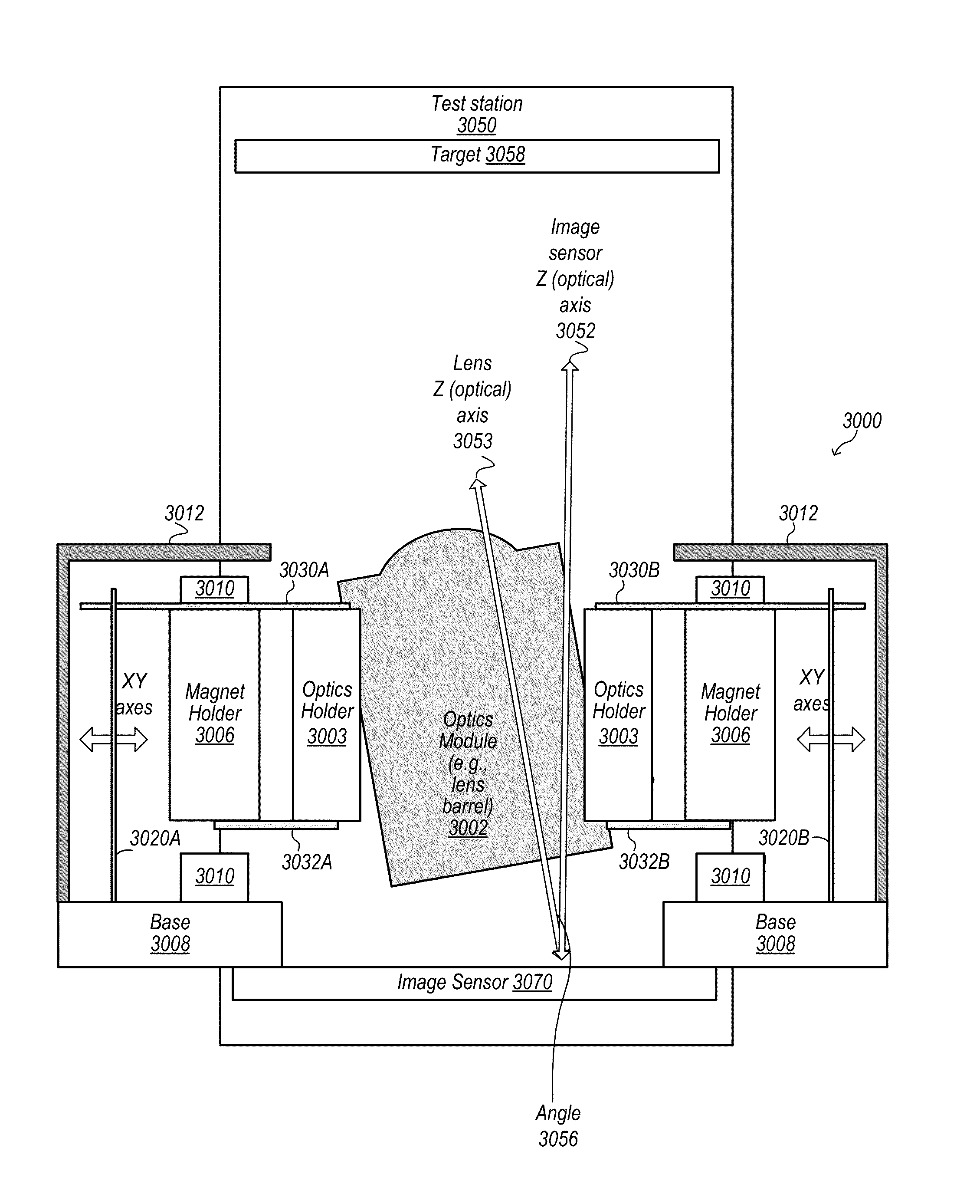
[0007]Some embodiments include methods for correcting optical alignment of components in a camera module for a multifunction device. In some embodiments, components of a camera module for use in a multifunction device are assembled on a test station. Some embodiments include a method that includes capturing a single test image, calculating from spatial frequency response data derived from the test image an optical tilt between the optical axis of a lens and an optical axis of the image sensor of the camera module, and mechanically adjusting an alignment of the lens and the optical axis of the image sensor of the camera module to reduce the optical tilt. In some embodiments, the capturing is performed using the components of the camera module, and the single test image contains visually encoded spatial frequency response data for characterizing the components of the camera module.
BRIEF DESCRIPTION OF THE DRAWINGS
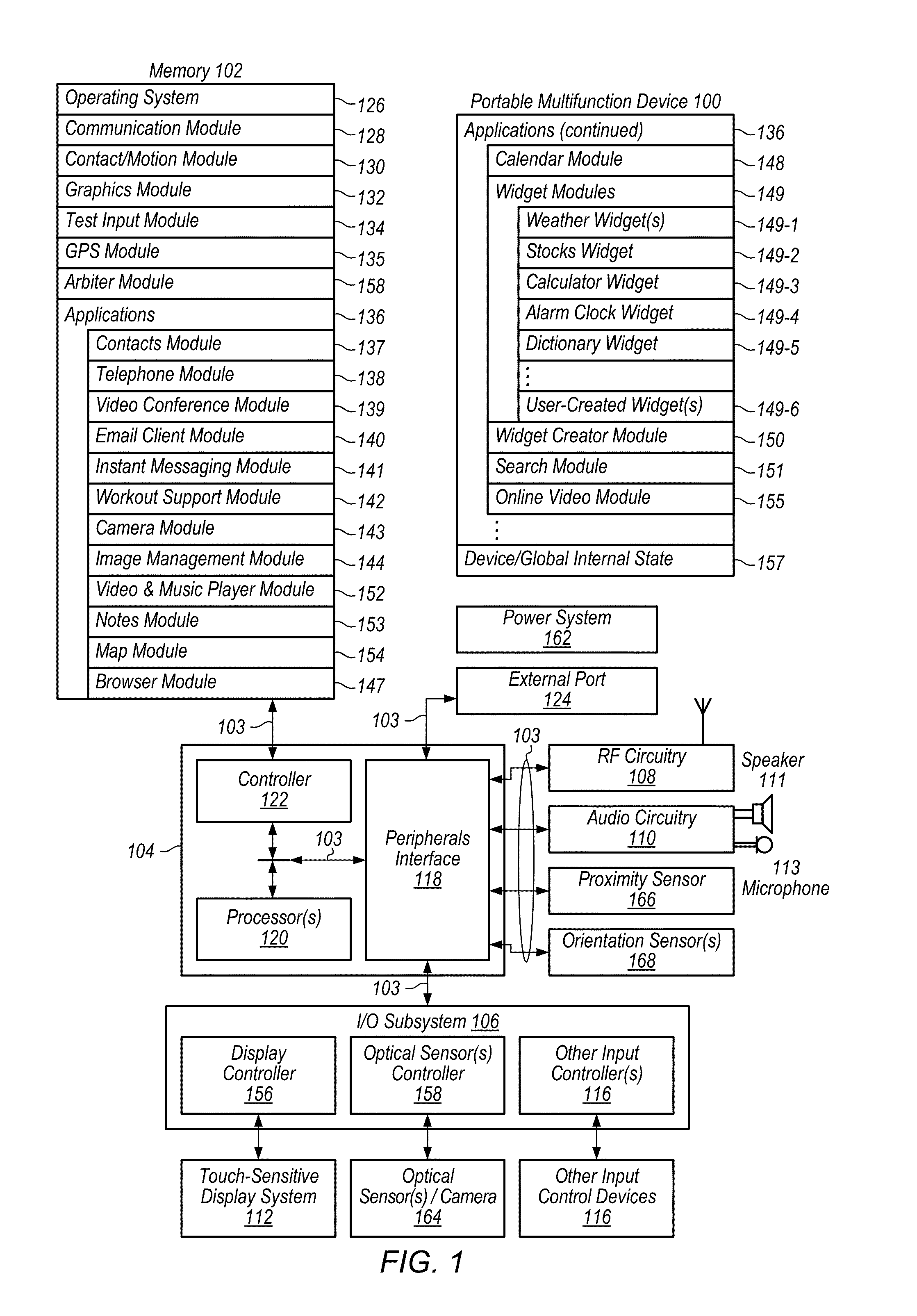
[0008]FIG. 1 illustrates a block diagram of a portable multifunction dev...
PUM
 Abstract
Description
Claims
Application Information