

Optical module
a technology of optical modules and optical alignment, applied in the field of optical modules, can solve problems such as reducing the efficiency of heat dissipation, and achieve the effect of good heat dissipation and precise optical alignmen
- Summary
- Abstract
- Description
- Claims
- Application Information
AI Technical Summary
Benefits of technology
Problems solved by technology
Method used
Image

Examples
first embodiment
[0025](First Embodiment)
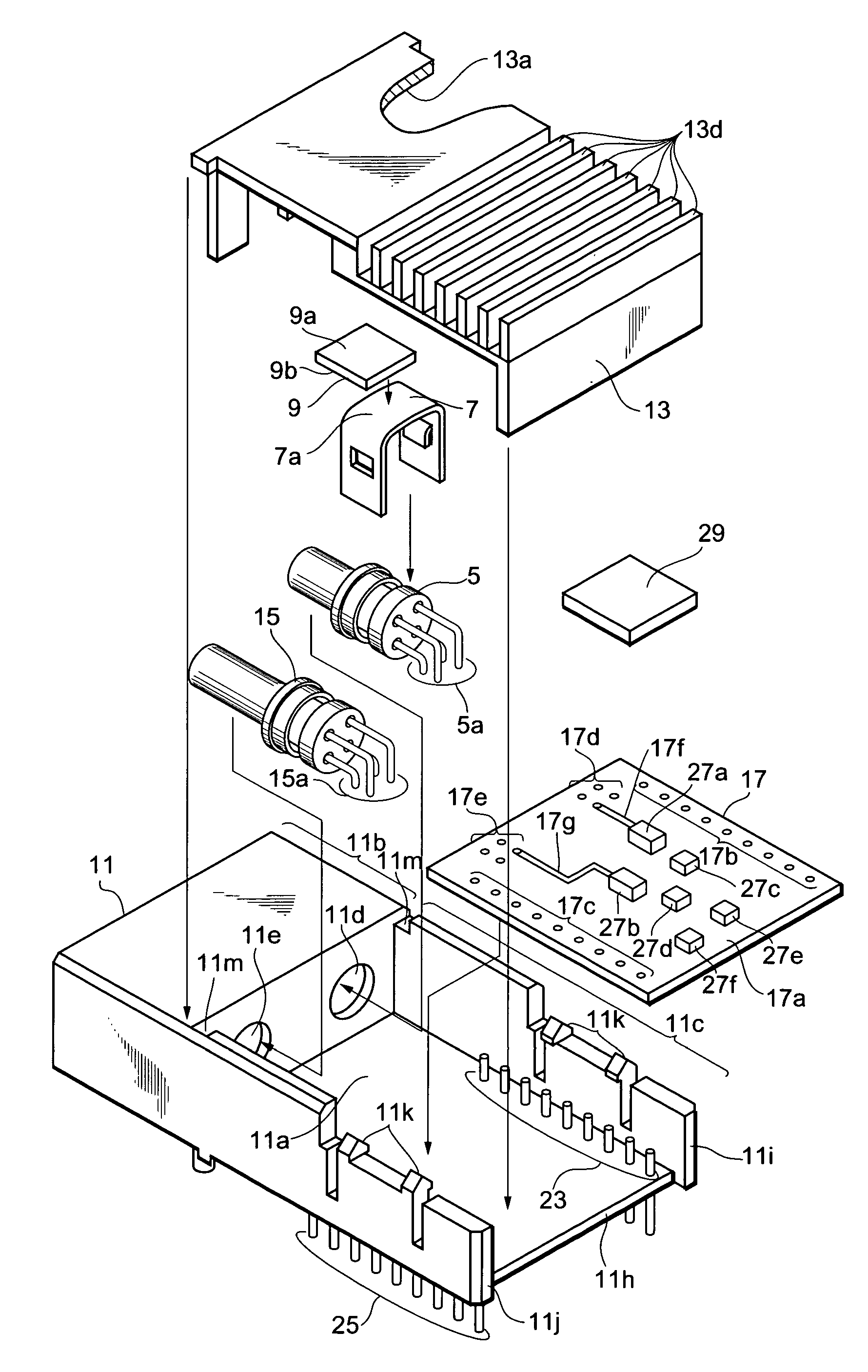
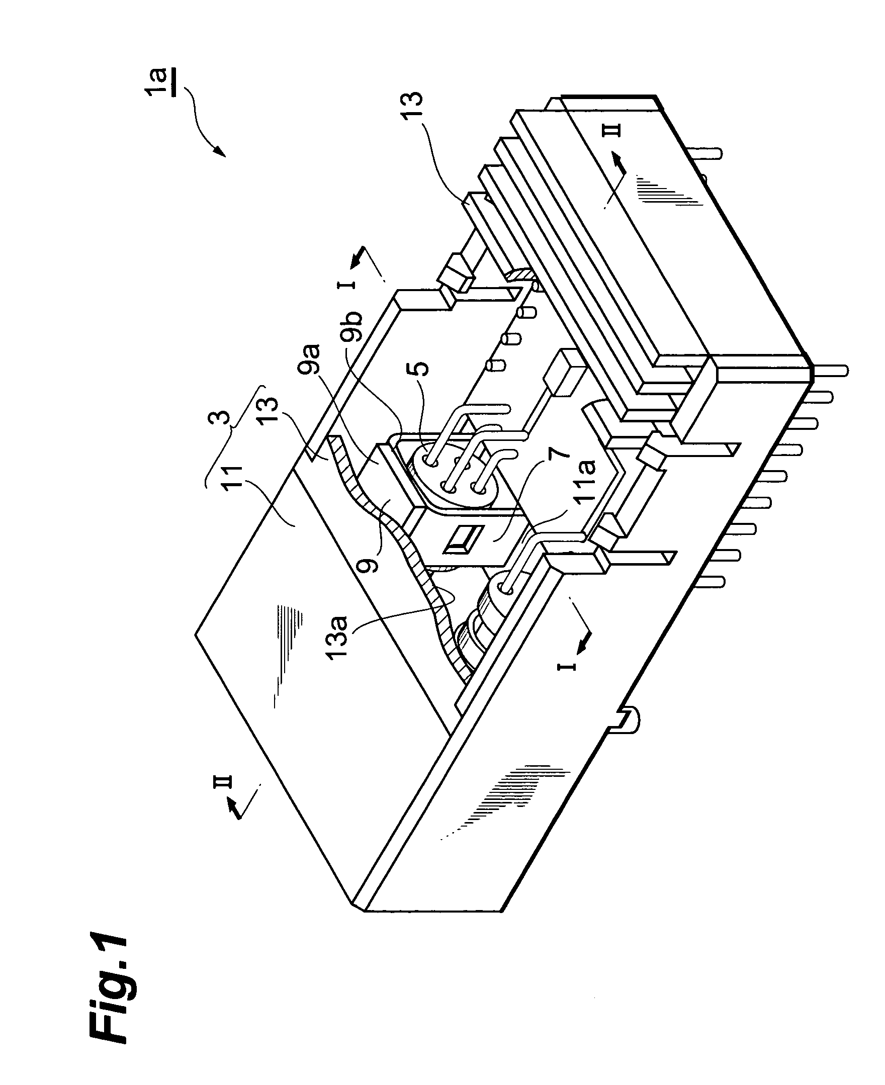
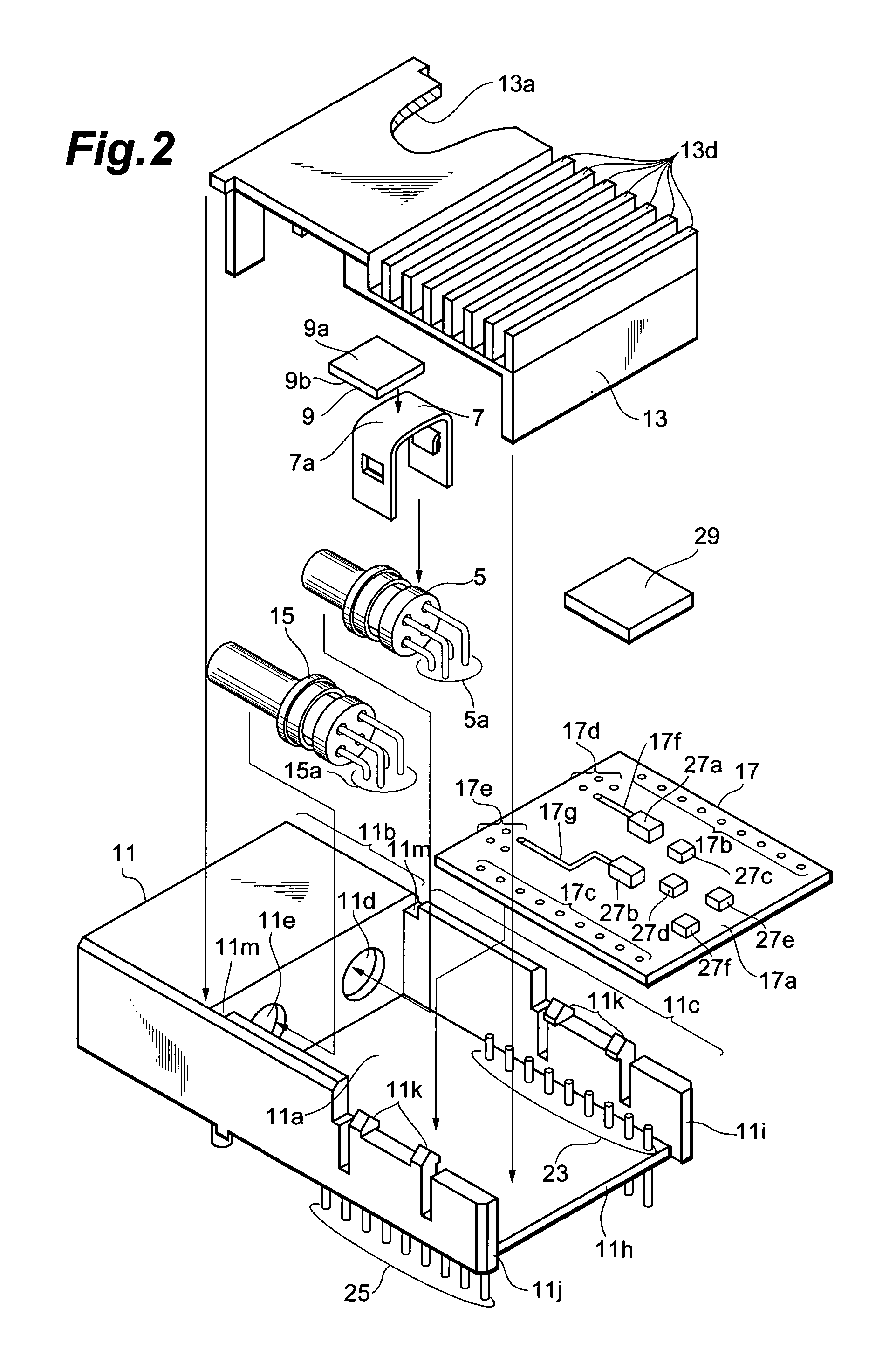
[0026]FIG. 1 is a partially perspective vie showing an optical module according to the first embodiment. FIG. 2 is an exploded view showing the components of an optical module according the first embodiment.
[0027]The optical module la comprises a housing 3, an optical subassembly 5, a support 7, and a thermal sheet 9. The housing 3 has a base 11 and a cover 13. The optical subassembly 5 is supported by the housing and is aligned in a predetermined axial direction. The support 7 is placed on a bottom surface 11a of the base 11. Since the thermal sheet 9 is sandwiched between the support 7 and the cover 13, the cover 13 and the support deform the thermal sheet 9. The repulsive stress due to the deformation is applied to the cover 13 and the support 7. The optical subassembly 5 receives this repulsive stress through the support 7.
[0028]Since the support 7 is in contact with the optical subassembly 5, the heat generated by the optical subassembly 5 is transmitted...
second embodiment
[0052](Second Embodiment)
[0053]FIGS. 7A and 7B are view showing a support 12 according to the second embodiment of the present invention.
[0054]In the support 12, a bridge 12a connects one end of a first leg portion 12b and one end of a second leg portion 12c with each other. The support 12 also has a finger 12g, which is curved so as to be in contact with a stem of the optical subassembly 5.
[0055]The support 12 has a connecting portion 12h that connects the first and / or second leg portions 12b and 12c with the finger 12g. The connecting portion 12h has first and second arms 12k and 12m. The first and second arms 12k and 12m are provided on sides 12i and 12j of the first and second leg portions 12b and 12c, respectively. The first arm 12k is connected to the second arm 12m by way of another bridge 12n. The finger 12g is located in the bridge 12n. The finger 12g extends from the inner edge facing to the bridge 12a and is then curved downwards. The finger 12g has a surface to be secure...
third embodiment
[0058](Third Embodiment)
[0059]FIGS. 8A and 8B are view showing a support 6 having a bridge 6a and first and second leg portions 6b and 6c. The support 6 has first and second fingers 6g and 6h that are secured to the optical subassembly 5 by solders. The first and second fingers 6g and 6h and the solders provide paths for heat transferring from the surface of the optical subassembly 5 to the support 6.
[0060]As shown in FIG. 8B, the first and second fingers 6g and 6h are curved inward so that gaps between the optical subassembly 5 and the first and second fingers 6g and 6h are formed when the optical subassembly 5 has been positioned. After positioning the support 6 and the optical subassembly 5 to each other, solder is supplied between the optical subassembly 5 and the first and second fingers 6g and 6h. The solders fill up with the gaps between the optical subassembly 5 and the first and second fingers 6g and 6h, respectively.
[0061]In the support 6 shown in FIG. 8A, the maximum leve...
PUM
 Abstract
Description
Claims
Application Information